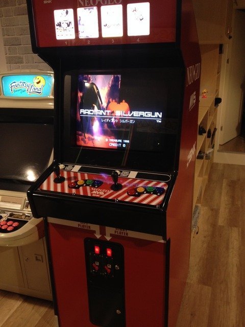
I received my ST-V multi last week.
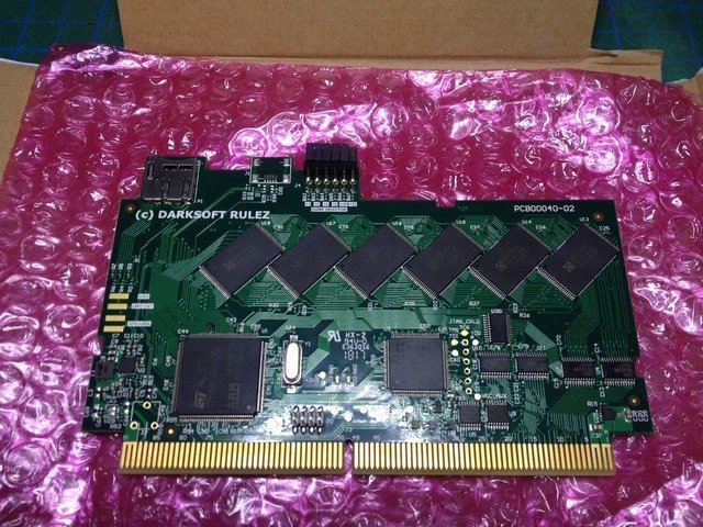
I was so excited, unpacked it, burned an SD card, adjusted the dip switches and plugged the multi into my spare ST-V mobo. Hurray! What a great product, thanks Darksoft for letting us play our favorite ST-V games on the real hardware...
After some testing, loading different games and playing on my test bench I decided to install the multi into my other ST-V mobo which is in the cabinet. Then I realized to change dip switches when the ST-V is "in" the cabinet will be a pain in the neck, especially when my daughter and her friends come to party in my home arcade and want me to change games (Yes, they think switching to another game in an arcade cabinet is as simple as opening an app in iphone!)
Anyway, I've read @'miisalo''s arduino based game selector (great product btw) posts I said to myself I need something like this. It is weekend and I was so excited that I do not have the patience to order that game selector and wait for it to be delivered I decided to make something similar from scratch.
I didn't t have any arduinos but have plenty of Atmega8 chips in my parts drawers and personally, I prefer to play with plain microcontrollers with hardcore C in my projects. So I decided to built something with the parts I already have...
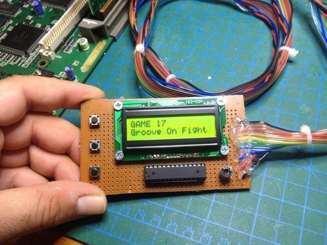
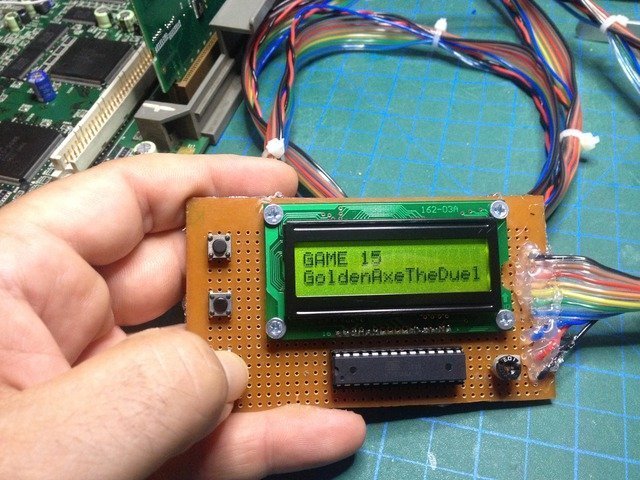
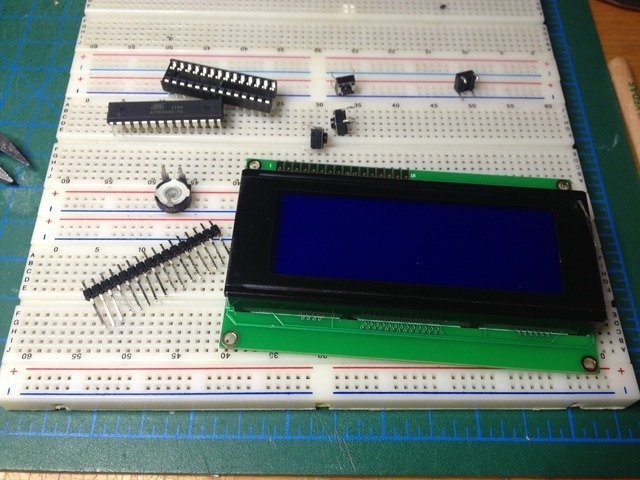
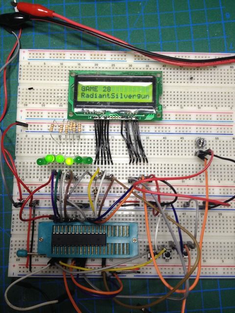
This is yet another game selector project with only a single Atmega8 chip, a cheap 16x2 LCD and three buttons. The firmware is written in C on Atmel Studio 7. (I didn't used that LCD on the photo. It turned out to be a 4 line LCD which I didn't wanted to waste it in such a simple project)
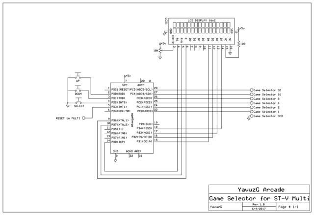
The schematic for the circuit is very simple. I tried to keep things simple. No fancy filter inductors, capacitors, debouncing stuff etc.

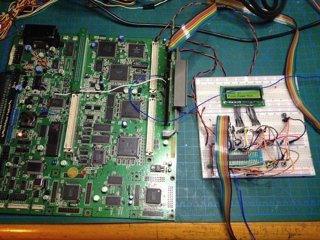
Here is the schematic built on the breadboard. First, tested the dip switch controls with LEDs...")

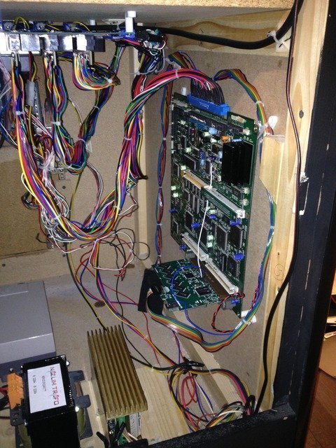
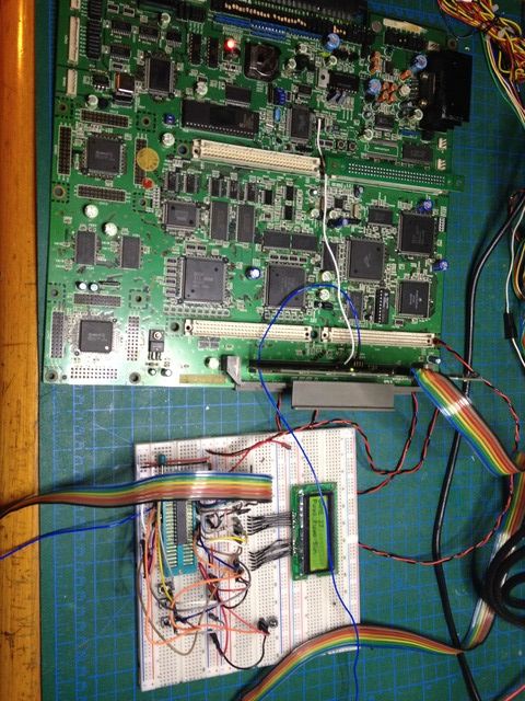
Then after a lot of testing on the firmware I connected the circuit to the ST-V + multi setup.
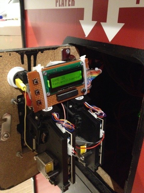
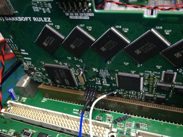
Ahh! Almost forgot to mention... The St-V multi obviously came with the new auto-reset firmware. I connected the auto-reset wire to the ST-V mobo and connected the reset line of the multi to my circuit.

With this, when I press the button to select a game, the microcontroller sets the dip switch and sends a 100ms reset signal to the multi. Then the multi keeps the ST-V reset line LOW while flashing the game and when finishes flashing the game it releases the reset line and the ST-V automatically boots. Basically this is exactly the CPS2 multi setup. No more power cycles or anything
For those who like to make things by themselves, attached are the high-res schematic image and Atmel Studio 7 project file and fuse settings.
Enjoy!
I was so excited, unpacked it, burned an SD card, adjusted the dip switches and plugged the multi into my spare ST-V mobo. Hurray! What a great product, thanks Darksoft for letting us play our favorite ST-V games on the real hardware...
After some testing, loading different games and playing on my test bench I decided to install the multi into my other ST-V mobo which is in the cabinet. Then I realized to change dip switches when the ST-V is "in" the cabinet will be a pain in the neck, especially when my daughter and her friends come to party in my home arcade and want me to change games (Yes, they think switching to another game in an arcade cabinet is as simple as opening an app in iphone!)
Anyway, I've read @'miisalo''s arduino based game selector (great product btw) posts I said to myself I need something like this. It is weekend and I was so excited that I do not have the patience to order that game selector and wait for it to be delivered I decided to make something similar from scratch.
I didn't t have any arduinos but have plenty of Atmega8 chips in my parts drawers and personally, I prefer to play with plain microcontrollers with hardcore C in my projects. So I decided to built something with the parts I already have...
This is yet another game selector project with only a single Atmega8 chip, a cheap 16x2 LCD and three buttons. The firmware is written in C on Atmel Studio 7. (I didn't used that LCD on the photo. It turned out to be a 4 line LCD which I didn't wanted to waste it in such a simple project)
The schematic for the circuit is very simple. I tried to keep things simple. No fancy filter inductors, capacitors, debouncing stuff etc.
Here is the schematic built on the breadboard. First, tested the dip switch controls with LEDs...
Then after a lot of testing on the firmware I connected the circuit to the ST-V + multi setup.
Ahh! Almost forgot to mention... The St-V multi obviously came with the new auto-reset firmware. I connected the auto-reset wire to the ST-V mobo and connected the reset line of the multi to my circuit.
With this, when I press the button to select a game, the microcontroller sets the dip switch and sends a 100ms reset signal to the multi. Then the multi keeps the ST-V reset line LOW while flashing the game and when finishes flashing the game it releases the reset line and the ST-V automatically boots. Basically this is exactly the CPS2 multi setup. No more power cycles or anything
For those who like to make things by themselves, attached are the high-res schematic image and Atmel Studio 7 project file and fuse settings.
Enjoy!
Attachments
Last edited:


")