What's new
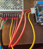
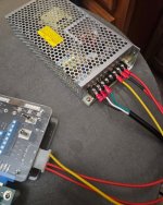
I believe your wiring is correct from what I can see in your pictures, but just to be clear, it should be:

Pin 1 on the SuperGun = +12V
Pin 2 on the SuperGun = GND
Pin 3 on the SuperGun = GND
Pin 4 on the SuperGun = +5V

Pin 3 on your SuperGun cable in the pictures is unpopulated, which isn't recommended (you should have two Grounds) but will work.

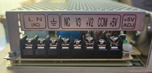
Long round pin Ground on AC plug (green wire) = FG
Wide blade Neutral on AC plug (white wire) = AC/N
Narrow blade Live on AC plug (black wire) = AC/L
 
I tried using a multimeter on the +5v section of my supergun, and got around 0.04 with the board connected.

You must have had your meter either set wrong or probed the wrong spots on the JAMMA connector.

You want your meter set to read DC Voltage - look for a V icon with a line next to it - it's Number 8 in this picture:
flk-webcard-dmm-dial-1500x1000.jpeg

Also make sure you have the black probe plugged into the black port on the meter labeled "COM" and the red probe plugged into the red port on the meter labeled "V" (assuming your meter has more than two probe ports).

Then with your game on, carefully touch the Red probe to Pin 3 or Pin 4 counting from the left side, and touch the Black probe to either Pin 1 or Pin 2. You should see a reading on the meter approximately the same as what the voltmeter is showing on the SuperGun.
JAMMA-Pinout-0003-JAMMA-Pinout.jpg
 
Oh, sorry probably should've included another shot of my new power supply. I don't see a +12V, but there is a COM I'll try connecting my black wire to (by which I assume you mean the one labeled "GND" on my supergun).

This is also the cable I was sent, without an extra GND wire. I've been getting by with the current games I own, but if you think I should invest in one with two GND connectors, I'll certainly look into what options are available.

Thanks as well for the layout you shared!
 

Attachments

  • Screenshot_20230807_192807_Gallery.jpg
    Screenshot_20230807_192807_Gallery.jpg
    392 KB · Views: 32
Hello! Recently I got myself a Bubble Symphony Japanese cartridge for my F3. I tried to load it up, however it's stuck on the "Push Test Switch" screen, with some glitches, and I can't get passed it.

The listing I bought this from showed the game in working condition, so I wonder if maybe I need to open the cartridge up and clean some things inside with rubbing alcohol or something?

My F3 motherboard IS working, and is a Japanese one that can load other games just fine. This is the first time I've ran into an issue like this, and any help in getting this working would be GREATLY appreciated!

Just noticed that your first post said that your F3 board is running other games just fine. F3 does use socketed chips on the cartridges so you can indeed open up the cartridge, carefully pry a socketed chip out with a small flat screwdriver, wipe the socket down with a Q Tip and isopropyl alcohol, and then reinstall the chip. Make sure the chip is reinstalled with the same orientation - there is a notch at one end that should match the notch on the socket.

Also check and make sure none of the connecting pins are bent.

If the cart still doesn't boot up afterwards - even after pressing the Test Switch - then you'd want to have the chips dumped with a chip programmer and compare them against MAME to make sure none of them are corrupt.
 
Oh, sorry probably should've included another shot of my new power supply. I don't see a +12V, but there is a COM I'll try connecting my black wire to (by which I assume you mean the one labeled "GND" on my supergun).

This is also the cable I was sent, without an extra GND wire. I've been getting by with the current games I own, but if you think I should invest in one with two GND connectors, I'll certainly look into what options are available.

Thanks as well for the layout you shared!

Oh man - that labeling on the new supply leaves something to be desired.

The connecting point with the flat lines is your Field Ground for the AC line.
COM is indeed Ground for Pins 2 and 3 on your SuperGun cable.
V2 is your +12V lead
V3 is a -5V lead if you ever end up with an older arcade board that needs -5V - not many do.
 
Thanks! So, to clarify, this is the right setup for the cords?

And thank you for the response on the F3 problem! Turns out I did just need go push the test button on the motherboard itself, but I'll keep that in mind in case I run into anything similar
 

Attachments

  • Screenshot_20230807_234526_Gallery.jpg
    Screenshot_20230807_234526_Gallery.jpg
    260.7 KB · Views: 35
I finally got around to getting everything hooked up, however the Mean Well RT-125A wouldn't turn on. I plugged everything back into my older one, and it worked perfectly, but this one doesn't seem to start up at all.

Any ideas? I also did look it up, and apparently some other people were having trouble getting this to work as well. One of which suggested this power supply instead:
https://www.arcadeshop.com/i/804/switching-power-supply-15-amp.htm

also in regards to my older power supply I've been using, there are SOME boards that will let me reach 5.0V, but yeah things like the F3 cap at around 4.77
 

Attachments

  • Screenshot_20230808_211748_Gallery.jpg
    Screenshot_20230808_211748_Gallery.jpg
    204.5 KB · Views: 35
Last edited:
It's probably set to 230V. Slide the switch on the side to 115V.
Sorry for the late response, was very busy last month. But yes! That did the trick, and my games are now able to be powered up to 5.00v. Thanks a ton!

Just to know for further references, is there a limit to how high this can go before possibly becoming dangerous to the boards?
 

Attachments

  • Screenshot_20230901_221038_Gallery.jpg
    Screenshot_20230901_221038_Gallery.jpg
    902.3 KB · Views: 25
Sorry for the late response, was very busy last month. But yes! That did the trick, and my games are now able to be powered up to 5.00v. Thanks a ton!

Just to know for further references, is there a limit to how high this can go before possibly becoming dangerous to the boards?

Every pcb is different but generally the 5v circuit has parts that only have max 2% tolerance. So you’re operating those parts out of spec outside of 4.9v-5.1v. This doesn’t kill them immediately but it hastens their demise, and they’re already 20+ years old at this point. You’d probably see immediate visual glitches lower than 4.7v or higher than 5.3v but they might not be permanent. Run 12v through a 5v circuit, which is easy to do if you goof up your wiring — that would likely kill something in the circuit immediately. Same result if you don’t key your jamma connector and plug something in upside-down or mis-aligned. https://www.retrorgb.com/tag/key

just adjust your power supply after you plug in a new pcb so the 5v line says 5.0v.
 
Back
Top