What's new

D@reD3vil

Beginner
Joined
Oct 30, 2023
Messages
11
Reaction score
1
Location
AZ
Hello
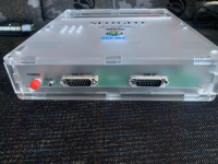
I recently bought a DIY Cbox kit. I was wondering if someone knows where I can find a tutorial or guide for the stereo sound mod. I know where the wires need to be connected to MV1C board I just don't know where to connect on the board in the back of the Cbox. This is the model I bought. Any help is greatly appreciated.

CBOX-3.png
CBOX.png
CBOX 2.png
 
I've got a couple of these kits around, and far as I know they're mono only. That being said, there are stereo RCA jacks. Currently it looks like they are wired together, so the same sound comes out of both. You could disconnect them from each other, which may involve cutting a trace on the PCB or simply disconnecting one of the wires that runs from the JAMMA connector to the rear IO (would have to trace the connection to see where the best place is). Really I think you would want to disconnect both of the RCA connections from the JAMMA to bypass the amplifier, then you tap into stereo from the chip just before the amp.

1704328547622.png
 
I found this guys guide but I cant make out what trace he cut. It looks like he only cut one but I would think a trace needs to be cut for each connection. Any thoughts?
View: https://www.youtube.com/watch?v=ys33lG3prag

That video shows the correct idea, but it's a different unit. May take me a bit, but I can pull out one of the ones like yours I have around and see if I can document where to make the cut.
 
OK, so took a quick look. On the bottom of the IO board there are two bridged connections that I think are where you will want to tap in for stereo.
IMG_1702 (1).jpeg


On the bottom of the mini-din 9 socket, I see pins 8 & 9 are bridged. This is the left and right audio. Then further back I see a bridged pad. I think that the cable connecting the JAMMA side to this IO side carries one or two wires for audio (can't tell for sure as with the bridged connections continuity spikes for both). So my thinking is you can remove the bridged pads/pins, cut the appropriate wire, and then connect two wires from the location I pictured previously.

I can play around a bit more with this if needed.

(oh, and despite the text on these boards they are NOT made by SNK and not made in Japan. Just more aliepxress lies!)

Edit: more info, the cable the connects the two PCBs. White is pin 10 and dark blue is pin L (center two wires). These are the mono audio positive and negative from the JAMMA connection. Cutting these two wires should isolate the audio output allowing you to tap in line level stereo.
IMG_1703.jpeg
 
Last edited:
After removing the two bridges, I can confirm that the left and right audio outputs are now isolated. You can add in the stereo connections as labeled.
IMG_1704.jpeg


So full steps...
1. Remove the solder from the bridged connections on the output board.
2. Cut the audio wires running from the JAMMA connector to the rear IO board.
3. Add wires from the audio chip on the MV1C to the pads on the bottom of the IO board (could also add them to the jacks directly like your video showed).

I think that would do it... there may be a better place to connect the audio however, it looks like the wiring from the JAMMA side to the IO side is connected to both pads. This would mean that there's an unused wire that's a second audio line. I checked and there is no connection from the wiring harness to the right audio channel.
Thank you for the help.
 
Thank you for the help.

Sure thing, let us know how it goes. Fair chance I’ll try it myself if I can find a MV1C around here that’s not being used for something.
 
Last edited:
Back
Top