You are using an out of date browser. It may not display this or other websites correctly.
You should upgrade or use an alternative browser.
You should upgrade or use an alternative browser.
- Thread starter Arthrimus
- Start date
Lemony Vengeance
Champion
This looks good, man! I was actually going through the process of doing something like this but I'm glad someone with a bit more know how than me beat me to the punch. Super glad I'll be able to point people to something as polished as this. Any word on what cost for the finished product will be?
also, super interested in that Cthulhu PCB as well.
One small question though, how are you routing the Home/guide and sel/back buttons on the boards? I had been using a multiplexer (the SN74ACT32N) that allowed for multiple button presses (for example B1+B2=B3) to bring use of these buttons back to the users. This particular IC allowed for up to 4 buttons to be brought back in through these button combos.
Last edited:
Thanks @Lemony Vengeance! I haven't done any math on pricing yet so I really can't say yet. Once all of the components of the board are finalized I can look at bulk pricing. The biggest unknown to me right now is PCB production. I want to do proper hard gold fingers on the JAMMA edge and that's going to be pricey. EDIT: I did some loose math and I'm hoping to target $100-$150. The cost of getting a run of hard gold plated PCBs made is staggering, but It the cost per unit scales down quickly with higher quantities. I'll be able to get more concrete numbers once I have a final design and can get an idea of how many to make.
As for select and home, I actually haven't thought about that. I routed select to the coin mech when I did the first layout for the board and I haven't revisited the controls since. The multiplexer idea is good. I had considered adding a microcontroller for button remapping so I might pursue that and build the button combos into the code. The only problem with this idea is that I have to figure out how to write on the fly button remapping code which has been eluding me on my other project, the RJ-45 to DB15 adapter.
As for select and home, I actually haven't thought about that. I routed select to the coin mech when I did the first layout for the board and I haven't revisited the controls since. The multiplexer idea is good. I had considered adding a microcontroller for button remapping so I might pursue that and build the button combos into the code. The only problem with this idea is that I have to figure out how to write on the fly button remapping code which has been eluding me on my other project, the RJ-45 to DB15 adapter.
Last edited:
Quick question for all interested parties. In the current design the volume pot controls both JAMMA and stereo RCA out. Is this preferable to most users or would it be better to have the volume pot only control JAMMA audio and leave the RCAs as line out?
I'm afraid I don't understand what you are asking. Can you clarify?I have one NNC like you and Jammafier. What's use external power supply or via JAMMA? It's seems cant use external power supply withit. And Can I use hack pad via JVS
JAMMA only. Keep RCA output audio at line level to be controlled in the cab's amp.Quick question for all interested parties. In the current design the volume pot controls both JAMMA and stereo RCA out. Is this preferable to most users or would it be better to have the volume pot only control JAMMA audio and leave the RCAs as line out?
Last edited:
Thanks for letting me know. Do I need to worry about loading the 12v rail? I'm not using it for anything at this time. As for the 5v rail I assume 1 amp of load would be sufficient to work with most power supplies?One more thing - this PCB won't load enough many arcade PSUs. As a fix, you could add a spot for a cement resistor.
What's the best way to order a couple of those MC Cthulhu boards? I have 2 of them but I really want that RJ45 connector default!
(also lol, this account I'm posting from isn't my own, I logged out and logged into my own account and now I'm back as "NeoXbit". I can't make it stop)
(also lol, this account I'm posting from isn't my own, I logged out and logged into my own account and now I'm back as "NeoXbit". I can't make it stop)
I now have them listed in my store. The price includes shipping to the continental USA.What's the best way to order a couple of those MC Cthulhu boards? I have 2 of them but I really want that RJ45 connector default!
(also lol, this account I'm posting from isn't my own, I logged out and logged into my own account and now I'm back as "NeoXbit". I can't make it stop)
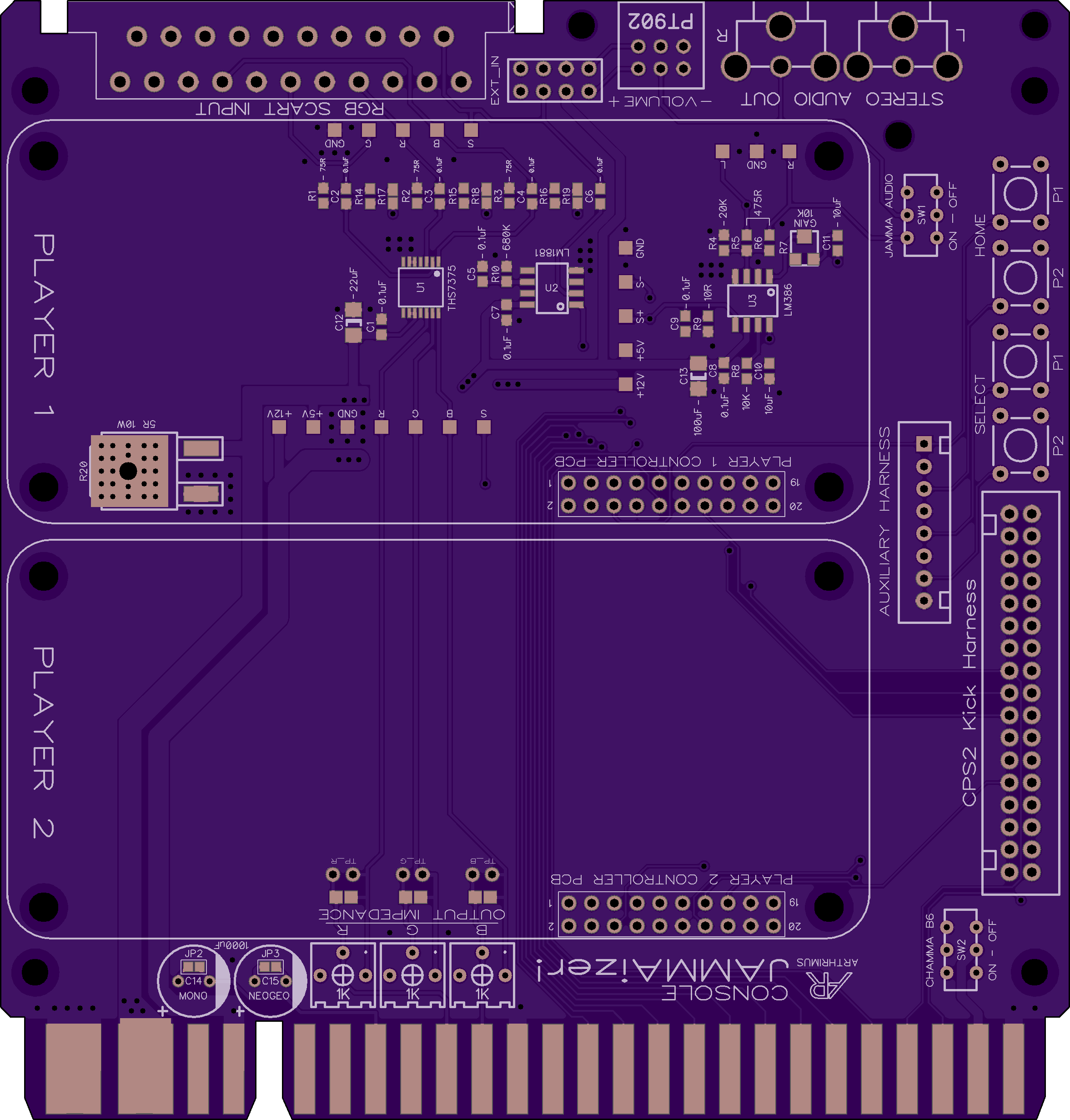
Now for some updates. Based on feedback from @Lemony Vengeance I have added some extra I/O to the PCB design. I was thinking about how to add select and home via button combinations but I'm not satisfied with any combination of the limited controls available. Therefore I think that the best solution is to add tact switches for P1 and P2 Select and Home, and also an auxiliary button harness connector so you have the option to wire extra buttons to your control panel. This required increasing the size of the PCB slightly.
Due to the suggestion of @RGB I've also added a load resistor on the 5v rail to help stabilize some arcade PSUs. I chose an SMD metal film resistor that has a thermal pad to help dissipate heat into the ground plane. I opted for this approach instead of a cement resistor due to size constraints. The resistor value may change, in my research about arcade PSUs it seems like 1 amp of load should be enough to stabilize the 5v rail on most PSUs, but if I can get away with a lesser load I would prefer that. Opinions on this would be appreciated.
Brentradio
Champion
Is there a list? I need to be on the list! Please add me to the list!
I want one!

I want one!
1A will be enough. Make sure you first test that resistor before producing larger PCB quantities, since it's right under the P1 board. 10W can get extremely hot (hopefully the large ground plane will help dissipate that heat).Due to the suggestion of @RGB I've also added a load resistor on the 5v rail to help stabilize some arcade PSUs. I chose an SMD metal film resistor that has a thermal pad to help dissipate heat into the ground plane. I opted for this approach instead of a cement resistor due to size constraints. The resistor value may change, in my research about arcade PSUs it seems like 1 amp of load should be enough to stabilize the 5v rail on most PSUs, but if I can get away with a lesser load I would prefer that. Opinions on this would be appreciated.
You can buy the chip from Paradise Arcade:Nice work
So for the EZ Cthulhu I need to harvest the chip from the original correct? There is no replacement for this part (yet)?
https://paradisearcadeshop.com/home...-cthulhu-to-mc-cthulhu-upgrade-kit-by-toodles
There you go:
https://www.retrorgb.com/console-jammaizer-by-arthrimus.html
PS: Can any of the admins please check what happened earlier? Someone posted as me, I know it wasn't intentional, but still.
https://www.retrorgb.com/console-jammaizer-by-arthrimus.html
PS: Can any of the admins please check what happened earlier? Someone posted as me, I know it wasn't intentional, but still.
I'm seeking opinions on a couple of design decisions that I'm faced with at this time.
- I have added a header for Player 1/2 Home and Select so you can wire additional buttons for Home and Select to your control panel. Should I also add pins on the header for P4 and K4 buttons for those who have 8 button control panels in their cabinets?
- Is the CPS2 kick harness the preferred option, or would it be better to have a CPS1 style kick harness connector and use adapters for CPS2 and other kick harness types? The CPS1 connector would save space on the board and make more room for an expanded auxiliary button harness. Also it seems like CPS1 is one of the easiest harness types to get adapters for.
Last edited:
Wouldn't hurt anything if you did and is a great idea.
- I have added a header for Player 1/2 Home and Select so you can wire additional buttons for Home and Select to your control panel. Should I also add pins on the header for P4 and K4 buttons for those who have 8 button control panels in their cabinets.
CPS2 in a landslide for the ubiquity of cabs out there that use CPS2 kick harness. CPS1 or other style connector only if foot print space on your PCB is at a premium. Not the case with your design however.
- Is the CPS2 kick harness the preferred option, or would it be better to have a CPS1 style kick harness connector and use adapters for CPS2 and other kick harness types. The CPS1 connector would save space on the board and make more room for an expanded auxiliary button harness. Also it seems like CPS1 is one of the easiest harness types to get adapters for.
EDIT: But either way, an adapter is easy to fashion. I've even created a PCB.
