What's new

kazuo

Grand Master
Joined
Sep 25, 2015
Messages
1,117
Reaction score
1,108
Location
United States / Thailand
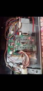
Anyone have a wiring diagram for this? Specifically, the 14 (?) pin white connector on the bottom right. Guessing that's the aux/kick harness for buttons 5 & 6. Diagram for the whole damn thing is fine, too. ;)

Appreciate any help!


?u=https%3A%2F%2Fi.imgur.com%2FYKhqlDdh.jpg
 
Off the top of my head (im 99.9% sure this is the way it goes), looking at the io the way its in the pic
  • 5V
  • 5V
  • 5V
  • P1 4 (P1 SW6 on 60 Pin Connector according to AO Wiki Pinout - not on jamma edge)
  • P1 5 (P1 SW7 on 60 Pin Connector according to AO Wiki Pinout - not on jamma edge)
  • P1 6 (P1 SW8 on 60 Pin Connector according to AO Wiki Pinout - not on jamma edge)
  • NC (At least not to the 60pin connector or the jamma edge)
  • P2 4 (P2 SW6 on 60 Pin Connector according to AO Wiki Pinout - not on jamma edge)
  • P2 5 (P2 SW7 on 60 Pin Connector according to AO Wiki Pinout - not on jamma edge)
  • P2 6 (P2 SW8 on 60 Pin Connector according to AO Wiki Pinout - not on jamma edge)
  • NC (At least not to the 60pin connector or the jamma edge)
  • GND
  • GND
  • GND
Ok, so I toned these out and this is the way they are connected.

Can someone verify these?
 
Last edited:
Where can one buy a kick harness for this? Or even the connector plus pins for DIYers.
 
Thanks @Derick2k! I'll probably log this on the AO Wiki with credit to you at some point.

Where can one buy a kick harness for this? Or even the connector plus pins for DIYers.
That was literally going to be my next question...

I suspect it's a JST NH (?), and you'll probably need some fancy crimpers for the pins...
 
Glad to help, I’ll double check when I get a chance, but I’m pretty sure it’s correct :) That reminds i should make some extra harnesses for these.
 
I can't remember the connector but I use the same kick harness cable for a Sega io. Just had to shave the guides of the side to fit between the extra pins
 
I'm having issues with this i/o or something. I can't get my ttx3 to register any buttons. I haven't been able to find common ground. This is a standard ttx3 running usf4 on a viewlix F. Any help is appreciated 🙏
 
Can you show us where you're pulling GND from? It should just work off that 14 pin connector. Derrick posted the pinout, it should be the same as the Sega JVS I/O commonly used during the Naomi era.

You can also use the 60 pin connector.
 
Can you show us where you're pulling GND from? It should just work off that 14 pin connector. Derrick posted the pinout, it should be the same as the Sega JVS I/O commonly used during the Naomi era.

You can also use the 60 pin connector.
My harness is stock, has a bit of modifications to it not done by me so I suspect some of my wiring is bad or the io is bad. Here's a pic
I'm not using the 14 pin connector as my harness is stock and using the 60 pin connector (G connector?)
I also have tried a working Rj45 ethernet cable to rule that out.
 

Attachments

  • Screenshot_20230213-091353_Gallery.jpg
    Screenshot_20230213-091353_Gallery.jpg
    121.7 KB · Views: 83
I’d much rather fix what you have than make an new one for ya if possible. That way you’re not dropping coin on a new one and I can help a bro :)
 
Back
Top