What's new
At no point did I suggest anyone should try and use the official adapter for this application. You may want to re-read.

I said that buying an original IO would be barely more expensive than a $100 adapter and a Type 3 IO.

I also said that the official adapter, which is only a handful of components less complicated costs $20.

But at no point suggested someone try to use a product for a different solution for this particular problem. And I will say again that it's silly because they're products for different problems. Obviously the one built for the problem at hand is going to perform better than the one built for an entirely different problem...
 
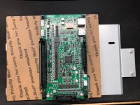
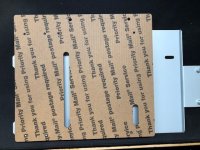
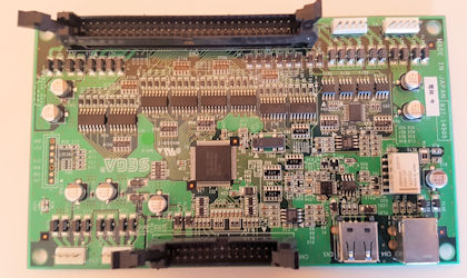
The hole spacing on my board is 37.5mm x 120mm and the board outline measures 48mm x 130mm. Hopefully that helps you plan your design file.
Yes it does, thanks. If things change please post about it.
 
This may not end up being an economically viable product to sell, I have more number crunching to do, but regardless I will finish the project and release the gerbers for it. If it's only ever a DIY project at least it will be the best option for someone trying to solve this problem.
At no point did I suggest anyone should try and use the official adapter for this application. You may want to re-read.

I said that buying an original IO would be barely more expensive than a $100 adapter and a Type 3 IO.

I also said that the official adapter, which is only a handful of components less complicated costs $20.

But at no point suggested someone try to use a product for a different solution for this particular problem. And I will say again that it's silly because they're products for different problems. Obviously the one built for the problem at hand is going to perform better than the one built for an entirely different problem...
Understood. I've read several threads here discussing the topic of adapting SEGA IO boards to Vewlix cabinets and inevitably the Taito adapter board gets suggested as the solution. I simply misread your intent in the original post and interpreted it as being a suggestion to use the Taito adapter instead. That being said the Taito adapter has been successfully used by other members here to adapt SEGA IO to Vewlix cabinets, it requires running a separate 5V power harness to the SEGA IO from the cabinet power supply. Regardless of what the Taito adapter was designed for people are trying to use it to perform this task and that's all that matters in this discussion. So no, I still don't think it's silly to explain the benefits of my solution. You can disagree, but to the next person who asks how to connect a SEGA IO to a Vewlix, the official Taito adapter will likely be suggested as the solution and knowing why a purpose built option exists will likely benefit them immensely.

EDIT: As an aside, here is you suggesting that someone should try and use the official adapter for this application. I happened to have this thread open in another tab earlier when I was researching for this project and came across it again just now.
The 60-pin connectors are even keyed differently so you can't accidentally plug Taito into Sega or vice-versa.
To adapt you need:
Taito part no. K91X1207B
taito.jpg
You can see where my misunderstanding came from right?
 
Last edited:
We'll agree to disagree on the one point. Though I do see yours. No ill will meant in any case.

I do hope it works out and sells great and helps a ton of people.
 
As far as "harnesses" go to connect the adapter board to the Sega I/O. I wouldn't put a whole lot of effort into them. They are all over ebay for under $10. Just make sure the 60pin connector on your adapter has the right orientation.

https://rover.ebay.com/rover/0/0/0?mpre=https://www.ebay.com/ulk/itm/171301705678
Yeah, that makes it a lot easier. The only custom harnesses that will need to be made will be the power harnesses for the SEGA IO.
:whistling: :whistling: :whistling:
https://www.digikey.com/product-detail/en/jst-sales-america-inc/A04SR04SR30K152A/455-3002-ND/6009378

:thumbsup:
 
I bought 3 for $120 a while ago. So yeah, 30-40. But when the group buy has brand new Taito ones at 180, that's only $40 from used Sega IO with adapter to getting a proper Taito one.
180 for a band new taito jvs board shipped to your house? Someone here was offering me one for that price but it was used and from what have read you can't get a taito jvs for less than 240.
It's something around 180 via the group buy on AO. I guess group discount? Dunno.
 
@Arthrimus was looking at layout, so I would suggest the following layout/changes if it makes sense to you.

txQBMVb.jpg

DBCBDEE0-035B-45C9-8BCD-8D76A9BC16C8.jpeg


The taito G harness is kinda short so it sits to the top left corner of the control panel. So this layout would help make it a straight forward connection scheme.
Relocation the power connectors would help in needing shorter harnesses, also think the layout flows a little better.

Another note, if you change your board size slightly to have a hole pattern of 28.5mm or 48mm x 145mm it can fit/mount right onto the studs on the left of the taito io plate.
 
Last edited:
Yep, now just rotate the Viewlix 60pin connector 180degrees and it will be perfect.
No can do on that request. Rotating the Vewlix harness connector would require a much larger PCB. The way it is set up now most of the connections are almost straight across the PCB, but if one of the harness connectors was flipped, all of those nice straight connections would turn into a nightmare of crisscrossing lines.
 
Sweet, that should work out pretty darn nice.

The only thing to look out for I guess is that the ribbon cable connectors are properly setup to connect properly when you put the boards side by side and interconnect them.
 
Yep, now just rotate the Viewlix 60pin connector 180degrees and it will be perfect.
No can do on that request. Rotating the Vewlix harness connector would require a much larger PCB. The way it is set up now most of the connections are almost straight across the PCB, but if one of the harness connectors was flipped, all of those nice straight connections would turn into a nightmare of crisscrossing lines.
ahh ok, no worries.
Quick mock up of an acrylic adapter plate to mount this board along with the sega io on a taito io plate. I will wait for Arthrimus to finish his design to finalize this.

2019-09-18_22-22-05.jpg
 
Last edited:
Quick mock up of an acrylic adapter plate to mount this board along with the sega io on a taito io plate. I will wait for Arthrimus to finish his design to finalize this.
2019-09-18_22-22-05.jpg
Looks awesome. Do the Type 1 and 2 IO boards fit the same hole pattern as the type 3?
 
Looks awesome. Do the Type 1 and 2 IO boards fit the same hole pattern as the type 3?
The Type 1 looks like it might, the type 2 looks like its a lot larger, but I unfortunately dont have Type 1 or 2 IO boards to test/measure. But if someone gives me accurate hole pattern measurements we could verify and could adjust this layout.

Once you have you production board layout/hole pattern/size I can finalize my design to work with it, since I want to test it in the cab, with the actual wires harnesses, etc..I might do some little tweaks to help with wire management and such.

Im also measuring up a minimal design to support the IO board(s) so as not to waste so much acrylic, basically like support/mounting rails/adapters.
 
Last edited:
The Type 1 looks like it might, the type 2 looks like its a lot larger, but I unfortunately dont have Type 1 or 2 IO boards to test/measure. But if someone gives me accurate hole pattern measurements we could verify and could adjust this layout.
Once you have you production board layout/hole pattern/size I can finalize my design to work with it, since I want to test it in the cab, with the actual wires harnesses, etc..I might do some little tweaks to help with wire management and such.
Oh yeah sorry about that, the Type 2 IO is a totally different beast. I was thinking of the Type 1.5 board that has an SMD IC instead of the DIP package.

837-14505-thumb.jpg


It looks like the type 3 board has 2 sets of mounting holes on the right hand side. The narrower hole spacing looks like it's probably a match for Type 1/1.5. Can you add those extra holes to your design?
 
Back
Top