biggestsonicfan
Professional
Begin repair log for Sega Versus City Billboard.
July '19:
.jpg")
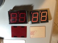
Billboard unit arrived "untested" from China after 2nd attempt to post. Very grimy and grungy.
Sep '19:
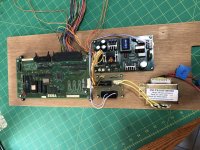
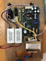
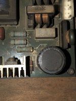
The AQB2A1-ZT3/6VDC-ND Solid State Relays on the power board look questionable, and replacement parts have been located and can be ordered if necessary: Sensata-Crydom CN240A05. In addition, two Blast City billboard power boards have been purchased as replacements if necessary. They are in much better condition and share the same PCB layout.
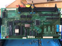
Used naval jelly to remove strange corrosion near C22 which removed some solder mask on some traces. On retrospect I probably shouldn't have done that but the continuity tests in some spots now work when they previously didn't. Removed tape covering Z80 processor and gave the board a wash with Krud Kutter, rinsing it off with water and a nylon brush. Removed a great deal of grime but also removed markings on both the Sega 315-5338A chip and labels. For historical purposes and possible reproduction, I am going to list the numbers here:

Ordered replacement 8-DIP switch as none of the switches will move, most likely due to rust/corrosion/grime built up inside.
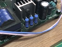
Ordered replacement caps for C1, C2, C3, and C4. Original caps marked as Sanyo 220μF 16V 105°C S.E.3N CZ. Replacement model is Suncon (Sanyo's current name) 220μF 16V 105°C S.E.5D CZ.
Removal of IC4 did not go well. Traces were damaged in attempting to desolder. The lack of proper equipment and recklessly using equipment I have is to blame. Using desoldering braids only removed solder from bottom half of board but there was enough residual solder that remained on the top half, where the IC package is located, that the chip would not come out. The legs were resoldered with fresh solder and a heated solder sucker was used. A rotating motion in an attempt to melt the solder with the heated sucker caused damage to the solder mask and traces. Ultimately much solder was removed the the IC would not budge. In an attempt to pry the IC package from the top, the pry tool broke cap C12 in half. Not wanting to damage traces further, I brought out a heat gun and using an IC pry-bar the chip was dislocated from the board.

Ordered replacement for IC12. Very strange ceramic caps from Mouser: Taiyo Yuden UP050B104K-A-BZ.
The crystal oscillator also looks to be in pretty bad shape and have located a replacement part on Alibaba. UPDATE: No parts in stock. Unsurprising...
The DIP28 Retention Contact was also damaged from contact with the soldering iron and I am considering replacing it as well.
All things considered, I lack the proper training and equipment to handle this type of rework. Rework that wasn't needed I might add. In wanting to replace an IC for cosmetic purposes I have created permanent cosmetic alterations to the board itself. Ironic.
Going forward I will be contacting Ken at irepairsega to see if he can fix this mess. His site says he does trace repair and I would prefer to have this in good, experienced hands rather than my own. I will collect all the parts I wish to have replaced and send them with the board to Ken to have him rework. I am a hobbyist at best and replacing capacitors and soldering arduino parts may be within my scope, but these professionally fabricated PCBs are a bit out of my league.
Will update when I sent a package to Ken.
July '19:
Billboard unit arrived "untested" from China after 2nd attempt to post. Very grimy and grungy.
Sep '19:
The AQB2A1-ZT3/6VDC-ND Solid State Relays on the power board look questionable, and replacement parts have been located and can be ordered if necessary: Sensata-Crydom CN240A05. In addition, two Blast City billboard power boards have been purchased as replacements if necessary. They are in much better condition and share the same PCB layout.
Used naval jelly to remove strange corrosion near C22 which removed some solder mask on some traces. On retrospect I probably shouldn't have done that but the continuity tests in some spots now work when they previously didn't. Removed tape covering Z80 processor and gave the board a wash with Krud Kutter, rinsing it off with water and a nylon brush. Removed a great deal of grime but also removed markings on both the Sega 315-5338A chip and labels. For historical purposes and possible reproduction, I am going to list the numbers here:
- Sega 315-5338A
- (Lot Code?) 9541 Z53
- 95AP 1026 (label left of Sega logo)
- 951101.07982E (label above CN5)
Ordered replacement 8-DIP switch as none of the switches will move, most likely due to rust/corrosion/grime built up inside.
Ordered replacement caps for C1, C2, C3, and C4. Original caps marked as Sanyo 220μF 16V 105°C S.E.3N CZ. Replacement model is Suncon (Sanyo's current name) 220μF 16V 105°C S.E.5D CZ.
Removal of IC4 did not go well. Traces were damaged in attempting to desolder. The lack of proper equipment and recklessly using equipment I have is to blame. Using desoldering braids only removed solder from bottom half of board but there was enough residual solder that remained on the top half, where the IC package is located, that the chip would not come out. The legs were resoldered with fresh solder and a heated solder sucker was used. A rotating motion in an attempt to melt the solder with the heated sucker caused damage to the solder mask and traces. Ultimately much solder was removed the the IC would not budge. In an attempt to pry the IC package from the top, the pry tool broke cap C12 in half. Not wanting to damage traces further, I brought out a heat gun and using an IC pry-bar the chip was dislocated from the board.
Ordered replacement for IC12. Very strange ceramic caps from Mouser: Taiyo Yuden UP050B104K-A-BZ.
The DIP28 Retention Contact was also damaged from contact with the soldering iron and I am considering replacing it as well.
All things considered, I lack the proper training and equipment to handle this type of rework. Rework that wasn't needed I might add. In wanting to replace an IC for cosmetic purposes I have created permanent cosmetic alterations to the board itself. Ironic.
Going forward I will be contacting Ken at irepairsega to see if he can fix this mess. His site says he does trace repair and I would prefer to have this in good, experienced hands rather than my own. I will collect all the parts I wish to have replaced and send them with the board to Ken to have him rework. I am a hobbyist at best and replacing capacitors and soldering arduino parts may be within my scope, but these professionally fabricated PCBs are a bit out of my league.
Will update when I sent a package to Ken.
Attachments
Last edited:
.JPG")
.JPG")
.JPG")