You are using an out of date browser. It may not display this or other websites correctly.
You should upgrade or use an alternative browser.
You should upgrade or use an alternative browser.
- Thread starter sk8er000
- Start date
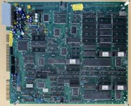
Related to IGS PGM, I re-capped my single board DEMON FRONT yesterday. Really nice board since it had uf and voltages marked on each capacitor slot so didn't even need a map.
Caps you need:
- 5x 470uf 16v
- 6x 10uf 25v
- 2x 100uf 25v
- 2x 47uf 16v
Originals were STONE labeled, never seen those before. They were in pristine condition by eye, and only two of them gave me the "the smell" when removed. No leaks on the PCB.

Caps you need:
- 5x 470uf 16v
- 6x 10uf 25v
- 2x 100uf 25v
- 2x 47uf 16v
Originals were STONE labeled, never seen those before. They were in pristine condition by eye, and only two of them gave me the "the smell" when removed. No leaks on the PCB.
Last edited:
pacoarcade
Professional
Crime Fighters (Konami)
C39 1000 16
C36 330 16
C50 10 16
C44 10 16
C40 10 16
C49 220 16
C41 100 16
C43 100 16
C39 1000 16
C36 330 16
C50 10 16
C44 10 16
C40 10 16
C49 220 16
C41 100 16
C43 100 16

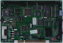
I'm trying to make a list for NA1, unfortunately I don't have my board yet and it has all capacitor replaced by radial one (for that reason I'll need a recap).so ... i measure the NA1 motherboard capacitors :
C43 is 470uf 10V lead space 5mm , dia 6mm , 10mm length (electrolytic capacitor)
C41 is 100uf 16V lead space 5mm , dia 4mm , 10mm length (electrolytic capacitor)
C33 is 220uf 6.3V lead space 5mm , dia 4mm , 10mm length (electrolytic capacitor)
C30 is 1000uf 16V lead space 5mm ,dia 11mm , 20mm length (electrolytic capacitor)
C6 is 100uf 16V lead space 5mm , dia 4mm , 10mm length(electrolytic capacitor)
all of these are rated on 85°C , but will work 105°C too
Now the hard part will be to put here the values and measure of that smd electrolytic caps
If somebody know how to interpretate value and can measure these smd electrolytic caps will be awesome
also in February , this year , i've made a comment about reccap this NA1 pcb , but will be fine to make this reccap proper list togheter , but after these notes they are :
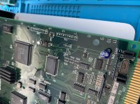
100uF / 6.3v - C8, C9, C10, C15, C16, C24, C25, C27 - dia 5mm , 5mm length
47uF / 16v - C39 - dia 5mm , 5mm length
22uF / 6.3v - C11, C14, C31, C32 - dia 3mm , 4mm length
2.2uF / 35v - C5, C23, C26, C28, C29, C38, C40 - dia 2mm , 4mm length
(these are my measurements - i've made it with a rulette , but if you have a caliper and can measure them proper , will be aweome)
For large image : Here
While double checking from your photo I see one error and a not showed cap. Can someone please doble check for me:
- C26 is not 2.2uf 35v but 4.7uF 25v
- C5 is not shown so I can't double check
- C6 is not shown and it's radial so I can't double check
Apart from that the list is ready to be added with the reference for every capacitor
Last edited:
AlxUnderBase
Enlightened
@sk8er000 ... what i didn't put in image have the correct value (i checked the value and measure the capacitor with my small rullete) and that's why i didn't put it in picture) , i just want a clear picture with all audio section ... if somebody with his NA board can check too to report here , will be awesome ...C41 & C6 are the same ... radial capacitors / electrolytic caps
C26 is indeed 4.7uf 25V (smd) - dia 3mm , 4mm length
C5 --- ??? on my pcb it shown on it (x4 1 50V)
C26 is indeed 4.7uf 25V (smd) - dia 3mm , 4mm length
C5 --- ??? on my pcb it shown on it (x4 1 50V)
Attachments
Last edited:
LittleLarrySellers
Professional
Got the correct polarized caps and just finished my System 16B board and she's all set for when my multi number gets called - "Welcome to bonus stage!"
Another silly newb question about caps, my basic understanding is the tantalum ones are also a type of electrolytic caps. Yet I normally don't see them listed or recommended for changing. Is that because generally these don't have the same failure rate or age much more gracefully?
Another silly newb question about caps, my basic understanding is the tantalum ones are also a type of electrolytic caps. Yet I normally don't see them listed or recommended for changing. Is that because generally these don't have the same failure rate or age much more gracefully?
Usually if the recapping is only preventive you can change only the regular capacitors and the super capacitor they are the ones than can damage the board due to leaking, generate faint audio and interferences. If the board doesn't present particular issues there's no need then.
pacoarcade
Professional
tantalum capacitors are supposed to have a really long life and they don't deteriorate so fast as the aluminum electrolytics, that's the reason they are not replaced if they are working fine. They are specially sensible to overvoltage and reverse voltage, though, and may explode or turn into pyrotechnics in these conditions.
I'm recapping my NA1 with the list made with @AlxUnderBase but my C26 is 2.2uF 50V and not 4.7uF 25v can someone confirm which one is the right one?
I'm tagging @Hammy since he has worked in many na1/na2
Thank you
I'm tagging @Hammy since he has worked in many na1/na2
Thank you
2.2UF

Nipron Co PSU - PS6146 (Sega Lindbergh Power Supply)
PS6146 No.01-0922A part No.400-5473(-xx)
Attached the original cap map as best as I could figure out, and a replacement/upgraded cap as best as was in-stock at digikey. Nearly all of them are upgrades, but I'll confirm they all work when they arrive.
https://www.digikey.com/short/z2jnjp
edit: all fit, seems fine. Not seeing much difference in my psu though. Wish I knew how to check performance better with my scope, maybe it’s time to watch some tutorial videos!
Attachments
Last edited:
SmokeMonster
Champion
Nastar Warrior / Rastan II care of TianFeng


First thanks to @sk8er000 for initiating this thread which is very helpful.
I double checked the system18 cap list against 3 boards I have (Alien Storm, Moonwalker and Shadow Dancer) as I plan to capkit them and found some things that do not match the list in the google sheet:
All 3 rom boards have 470uf 16V capacitors for C5, C6, C7, C8 with 5mm lead-spacing. The quantity table should list five 100uf 16V caps instead of nine and four more 470uf 16V caps.

I think there's a typo for C49 which is 1uf 50V cap (not 16V), the total for this cap value in the quantity table is right though.
On the 3 main boards C145 was a 47uf 16V cap (minor as it's ok to have 25V listed on the google sheet)
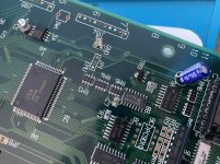
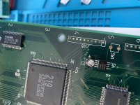
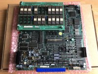
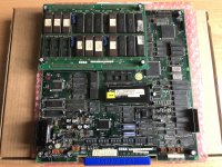
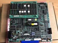
Also it looks like there are 2 different revisions of the main board (I attached some pictures of the 3 boards): on the revision which was used for the cap-list there's an MCU, 3 xtals and a CN9 port while on the other revision there are only 2 xtals and no MCU / CN9 port. The difference for the cap-list is that there's no C132 but a C2 instead (with the same specs) which is located next to the CPU.
I double checked the system18 cap list against 3 boards I have (Alien Storm, Moonwalker and Shadow Dancer) as I plan to capkit them and found some things that do not match the list in the google sheet:
All 3 rom boards have 470uf 16V capacitors for C5, C6, C7, C8 with 5mm lead-spacing. The quantity table should list five 100uf 16V caps instead of nine and four more 470uf 16V caps.
I think there's a typo for C49 which is 1uf 50V cap (not 16V), the total for this cap value in the quantity table is right though.
On the 3 main boards C145 was a 47uf 16V cap (minor as it's ok to have 25V listed on the google sheet)
Also it looks like there are 2 different revisions of the main board (I attached some pictures of the 3 boards): on the revision which was used for the cap-list there's an MCU, 3 xtals and a CN9 port while on the other revision there are only 2 xtals and no MCU / CN9 port. The difference for the cap-list is that there's no C132 but a C2 instead (with the same specs) which is located next to the CPU.
Attachments
thank you for your corrections, I'll double check the list and my PCB. The only difference that I immediately notice is that you have 171-5874 ROM board for all your games and I have a 171-5987 so it may differ, in that case I'll add both modelsFirst thanks to @sk8er000 for initiating this thread which is very helpful.
I double checked the system18 cap list against 3 boards I have (Alien Storm, Moonwalker and Shadow Dancer) as I plan to capkit them and found some things that do not match the list in the google sheet:
All 3 rom boards have 470uf 16V capacitors for C5, C6, C7, C8 with 5mm lead-spacing. The quantity table should list five 100uf 16V caps instead of nine and four more 470uf 16V caps.
I think there's a typo for C49 which is 1uf 50V cap (not 16V), the total for this cap value in the quantity table is right though.
On the 3 main boards C145 was a 47uf 16V cap (minor as it's ok to have 25V listed on the google sheet)
Also it looks like there are 2 different revisions of the main board (I attached some pictures of the 3 boards): on the revision which was used for the cap-list there's an MCU, 3 xtals and a CN9 port while on the other revision there are only 2 xtals and no MCU / CN9 port. The difference for the cap-list is that there's no C132 but a C2 instead (with the same specs) which is located next to the CPU.
AlxUnderBase
Enlightened
yes buddy , we have that motherboard with 3 crystals and the rom board who uses the 4 x 100uf 16v. and 22 roms locations vs 470uf 16v with 20 roms locationsthank you for your corrections, I'll double check the list and my PCB. The only difference that I immediately notice is that you have 171-5874 ROM board for all your games and I have a 171-5987 so it may differ, in that case I'll add both modelsFirst thanks to @sk8er000 for initiating this thread which is very helpful.
I double checked the system18 cap list against 3 boards I have (Alien Storm, Moonwalker and Shadow Dancer) as I plan to capkit them and found some things that do not match the list in the google sheet:
All 3 rom boards have 470uf 16V capacitors for C5, C6, C7, C8 with 5mm lead-spacing. The quantity table should list five 100uf 16V caps instead of nine and four more 470uf 16V caps.
I think there's a typo for C49 which is 1uf 50V cap (not 16V), the total for this cap value in the quantity table is right though.
On the 3 main boards C145 was a 47uf 16V cap (minor as it's ok to have 25V listed on the google sheet)
Also it looks like there are 2 different revisions of the main board (I attached some pictures of the 3 boards): on the revision which was used for the cap-list there's an MCU, 3 xtals and a CN9 port while on the other revision there are only 2 xtals and no MCU / CN9 port. The difference for the cap-list is that there's no C132 but a C2 instead (with the same specs) which is located next to the CPU.
Attachments
AlxUnderBase
Enlightened
I've compiled list for Namco System 2 motherboard who keeps Golly Ghost sub-board (theres no capacitors) since i intend very soon to replace the caps from mine:
Main Pcb all are radial :
* C1 - 470uf 10V (Dia 6mm , Lead Spacing 4mm , Lenght 10mm)
* C2 - 0.47uf 50V (Dia 4mm , Lead Spacing 2mm , Lenght 10mm)
* C3 - 0.47uf 50V (Dia 4mm , Lead Spacing 2mm , Lenght 10mm)
* C14 - 1uf 50V (Dia 4mm , Lead Spacing 2mm , Lenght 10mm)
* C15 - 100uf 10V (Dia 4mm , Lead Spacing 2mm , Lenght 10mm)
* C26 - 100uf 16V (Dia 5mm , Lead Spacing 3mm , Lenght 10mm)
* C27 - 10uf 16V (Dia 4mm , Lead Spacing 3mm , Lenght 10mm)
* C29 - 22uf 16V (Dia 4mm , Lead Spacing 3mm , Lenght 10mm)
* C30 - 10uf 16V (Dia 4mm , Lead Spacing 3mm , Lenght 10mm)
* C31 - 22uf 16V (Dia 4mm , Lead Spacing 3mm , Lenght 10mm)
* C32 - 22uf 16V (Dia 4mm , Lead Spacing 3mm , Lenght 10mm)
* C33 - 10uf 16V (Dia 4mm , Lead Spacing 3mm , Lenght 10mm)
* C38 - 10uf 16V (Dia 4mm , Lead Spacing 2mm , Lenght 10mm)
* C39 - 2.2uf 50V (Dia 4mm , Lead Spacing 2mm , Lenght 10mm)
* C50 - 100uf 6.3V (Dia 4mm , Lead Spacing 2mm , Lenght 10mm)
* C51 - 100uf 6.3V (Dia 4mm , Lead Spacing 2mm , Lenght 10mm)
* C52 - 2.2uf 50V (Dia 4mm , Lead Spacing 2mm , Lenght 10mm)
* C53 - 10uf 16V (Dia 4mm , Lead Spacing 2mm , Lenght 10mm)
* C54 - 10uf 16V (Dia 4mm , Lead Spacing 2mm , Lenght 10mm)
* C55 - 47uf 16V (Dia 4mm , Lead Spacing 2mm , Lenght 10mm)
* C59 - 2.2uf 50V (Dia 4mm , Lead Spacing 2mm , Lenght 10mm)
* C60 - 2.2uf 50V (Dia 4mm , Lead Spacing 2mm , Lenght 10mm)
* C61 - 2.2uf 50V (Dia 4mm , Lead Spacing 2mm , Lenght 10mm)
* C62 - 2.2uf 50V (Dia 4mm , Lead Spacing 2mm , Lenght 10mm)
* C63 - 47uf 16V (Dia 4mm , Lead Spacing 2mm , Lenght 10mm)
* C66 - 100uf 6.3V (Dia 4mm , Lead Spacing 2mm , Lenght 10mm)
* C67 - 100uf 6.3V (Dia 4mm , Lead Spacing 2mm , Lenght 8mm)
* C70 - 220uf 10V (Dia 5mm , Lead Spacing 3mm , Lenght 10mm)
* C72 - 2200uf 16V (Dia 10mm , Lead Spacing 5mm , Lenght 22mm)
Video board all are axial :
* C1 - 470uf 6.3V (Dia 6mm , Lead Spacing 30mm , Lenght 10mm)
* C2 - 470uf 6.3V (Dia 6mm , Lead Spacing 30mm , Lenght 10mm)
ps : Please guys , if you have in possesion a Namco System 2 pcb and wanna add your toughts about my notes and off course , please let me know if are some mistakes on what i've noted here !
Attachments
Last edited:
