What's new

invzim

Champion
Joined
Apr 9, 2016
Messages
1,063
Reaction score
2,522
Location
Oslo, Norway
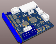
Something I've been toying with on/off for quite some time. The project got a lot more real as I got into Altium, this thing would be very very hard to do properly in Eagle..
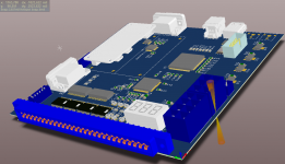
Capture.PNG

Main goal is to have an available and good JVS2JAMMA converter that's better than the riverservice/namco/konami one - with upscaling better than XRGB2, which pretty much snaps into a Naomi Universal cab with hopefully zero user configuration.

Some features I'm pretty confident with:
  • Very good lag-free upscaling from jamma to 31k VGA for CRT's - using a Cyclone IV FPGA
  • 5V TTL sync on output instead of 3.3V which seems normal on most FPGA projects
  • Central control plane using RaspberryPI Zero/A+
  • JVS input synced to vsync
  • various remapping/autofire stuff
  • Control input from JVS and USB - so you can hook up a joypad/keyboard if you're so inclined
  • Auto detection of modes, and if the bandwidth on the board is good enough a 'super-scan' mode in case mode detection fails
  • High quality video ADC and DAC from Analog Devices
  • space for LED voltmeter, with connectors for for 5V and 12V readings
  • -5V generation
  • Coining up that works with Cave SH-3 :)
  • kick from JST-XH like RGB's very nice HAS
Some optional features which are borderline useless and not primary:
  • Since its' pretty much free, I added a second JVS port so it can work as a JVS IO board too for those that like to tinker.
  • 0.7/1V input for consoles and 25k/31K stuff
  • PWM output for arkanoid, so I can finally play Arkanoid revenge of DOH (using e.g. mouse or trackball on Virtua Golf panel)

It's not going to be cheap, as it's a 4 layer PCB and the cost of the components are adding up quite a bit - but this is mostly something I make because I want it and I'm not even sure it will be produced for general availability like the JVS-pAC.

Hoping to have a working proto assembled this summer.
 
Oh man, so happy to see you finally got back to this! Good luck, this will be awesome.
 
Definitely interested- what screen modes will you be able to support, both on input and output sides?
 
Whaooo, you guys in this forum are definitely hot !

What I would suggest as a nice feature would be to let a jumper to bypass the upscaler. Cabs with tri-frequencies monitors or the small JVS cabs like Mushiking, Dinoking and Loveberry that cannot handle the 31khz h-frequency would benefit from this feature.

Got a jamma2jvs PCB from River Service into my Mushiking and it's true it's far from perfection.
 
This sounds awesome. I also 2nd the idea of having the upscaler be optional or able to be bypassed. Net cities handle 15khz just fine for example.

The Konami and Namco adapters have always been hard to find and quite expensive. If you come in under 200 to 300 USD I'm sure you'd have people wanting to buy these.
 
This is really a great news.
:)
Hope to see this very soon.
 
The upscaler is kind of the core of this thingy and what makes it expensive. With just controls it could be a 2 layer PCB and would be designed a bit different.

How should the video output from a non-scaling variant be - sync split to H/V and downshifted to vga-levels and output via a VGA connector + 'raw' video on a 5pin something?

I should probably get the upscaling thingy done first and see how much the components and PCB will cost will be before starting a potential simpler version.

Another option could be to just output 15k - but pipe it through the FPGA. I hope to be able to make a an option for pixel-perfect wider image by using clock scaling, i.e. keep the horizontal frequency identical but having fewer (black) pixels on output. The picture will be pretty much identical, this is a 15k output from the DAC/ADC combo: http://kirurg.org/drop/IMG_3324.JPG


As it's raspberry for controls - the non-interactive options would likely be a different SD card image, or just a text-file on it that can be edited.
 
I use the namco adapter currently, and I don't even think it splits sync (it might, but I don't think it does).

As far as passing through 15khz, handling that the way the old francob looms did would probably be fine (just use resistors to drop the level and wire to a dsub). It probably wouldn't hurt anything to split to h/v sync if you wanted to.
 
I'm away from my toys working abroad, so I have a request for some help.

Game input normally works like this:
https://cdn.sparkfun.com/assets/6/f/b/c/7/511568b6ce395f1b40000000.jpg

As I need to emulate the button, the value of the pull-up resistor is of some interest to know how much current I need to sink.

So far, I've gathered data for cps1/cps2 and an r-type bootleg - all 1k, which SHOULD be the typical value.

For a lot of games, this can be measured simply by measuring the Ohm/Resistance between 5V and e.g. pin18 on the jamma edge without anything connected.
So if you have a game handy and know how to use a multimeter, all measurements are most welcome!
 
Awesome!

How about some good scanlines generation? :)
 
A few more components added, design solidifying quite a bit. It will definitely be a 4 layer board, but has been shrunk down to 130x130mm - still a rather large PCB. Given the all the connectors on the edge, I think this is reasonable size.


Untitled.png

Ditched Raspberry A+, going for zero only.

TODO:
  • Decide on FPGA configuration scheme
  • Figure out the ultimate audio attenuation circuit
 
Looks incredible, very interested in this. Would be just what I'd need if I end up not getting a 15k cab in the future.
 
Any idea of a projected cost for the final product?
 
Back
Top