There is no reason to move them if it's wired that way, it will work just fine. There are basically two parallel ways to wire buttons 4 and 5, and some ops do the one connector way if they're not running fighters that need all 6, and then end up adding the 6th off the kick later.
You are using an out of date browser. It may not display this or other websites correctly.
You should upgrade or use an alternative browser.
You should upgrade or use an alternative browser.
- Thread starter MeNewVegas
- Start date
MeNewVegas
Student
So I did more investigating to see what the wiring was.
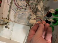
So the blue striped and yellow striped wires are in the 10 bit connector. They look like the are linked to connectors for 2 of the P1 4-6 buttons. Im still not sure why button 2 wasnt working for either player.
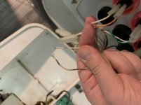
I also found these frayed wires. They are for P2. One is black stirped and one is plain white. From what I can gather they are for a single button. I assume these are meant for the 10 bit option?
So the blue striped and yellow striped wires are in the 10 bit connector. They look like the are linked to connectors for 2 of the P1 4-6 buttons. Im still not sure why button 2 wasnt working for either player.
I also found these frayed wires. They are for P2. One is black stirped and one is plain white. From what I can gather they are for a single button. I assume these are meant for the 10 bit option?
Attachments
MeNewVegas
Student
again lemony just made a ton of harness for extra connector I believe
Sure, and the Blast City is one of them. It has the 4th and 5th button on the jamma edge going to the 1P and 2P connectors in the CP. This is great for MVS, PGM and Atomiswave.It's very possible it all works as is, because you'll find some cabs have wired buttons 4 and 5 on the main connector, and only 6 off the kick harness.
However, it's not great for Pandora. Pandora is Chamma. It has the 6th button where normally you have GND. It doesn't have a separate kick harness connector. So if you want to connect a Pandora to a normal, unmodified jamma harness, you need an adapter. Like this one:
https://www.mikesarcade.com/cgi-bin/store.pl?sku=JA-CHAMMA
If he gets that or something like it, he'll need a fully populated aux connector harness.The CHAMMA to JAMMA adapter moves the extra buttons to a proper CPS1 Kick harness plug on the adapter, allowing you to play the board in a standard JAMMA cabinet.
Can use a standard CPS1/SFII Kick harness for Player one and Two's button 4, 5 and 6.
If there's an adapter that passes the 4th and 5th button through and only moves the 6th button to a kick harness connector, then yes, you're right, that'll work as is, provided he has 1P and 2P harnesses with the needed 4th and 5th button wiring.
Also, the AUX connector is wired "wrong", so if he wants to connect button #6 for 1P and 2P, he'll need to use pin 3 and pin 5 on the CN8.
TL;DR: the current wiring is a mess and I would start over.
Last edited:
MeNewVegas
Student
I will PM Lemony to see what he has.again lemony just made a ton of harness for extra connector I believe
MeNewVegas
Student
I will be running Jamma2Pi. Will I need a fully populated AUX for that? If so what are the names of the P1 and P2 connectors and do they take the same pins as the AUX connector?Sure, and the Blast City is one of them. It has the 4th and 5th button on the jamma edge going to the 1P and 2P connectors in the CP. This is great for MVS, PGM and Atomiswave.It's very possible it all works as is, because you'll find some cabs have wired buttons 4 and 5 on the main connector, and only 6 off the kick harness.
However, it's not great for Pandora. Pandora is Chamma. It has the 6th button where normally you have GND. It doesn't have a separate kick harness connector. So if you want to connect a Pandora to a normal, unmodified jamma harness, you need an adapter. Like this one:
https://www.mikesarcade.com/cgi-bin/store.pl?sku=JA-CHAMMA
If he gets that or something like it, he'll need a fully populated aux connector harness.The CHAMMA to JAMMA adapter moves the extra buttons to a proper CPS1 Kick harness plug on the adapter, allowing you to play the board in a standard JAMMA cabinet.
Can use a standard CPS1/SFII Kick harness for Player one and Two's button 4, 5 and 6.
If there's an adapter that passes the 4th and 5th button through and only moves the 6th button to a kick harness connector, then yes, you're right, that'll work as is, provided he has 1P and 2P harnesses with the needed 4th and 5th button wiring.
Also, the AUX connector is wired "wrong", so if he wants to connect button #6 for 1P and 2P, he'll need to use pin 3 and pin 5 on the CN8.
TL;DR: the current wiring is a mess and I would start over.
I guess you mean Pi2Jamma? According to the site:I will be running Jamma2Pi. Will I need a fully populated AUX for that?
So in this case you need fully populated 1P and 2P wiring harnesses. The kick harness wiring you have is sufficient. The 6th button goes from the screw terminals to pin 3 and pin 5 on CN8.Button 4, 5 for both Player is on Jamma Connector Pin 25 and 26 and bottom side. Button 6 for both players is available on the screw terminal. The screw terminals has also one GND.
They're all AMP UP connectors. P1 and P2 connectors are 12-pin, the AUX connector is 10-pin.If so what are the names of the P1 and P2 connectors and do they take the same pins as the AUX connector?
https://wiki.arcadeotaku.com/w/Sega_Blast_City_Wiring_Guide (see top image for pinout)
https://wiki.arcadeotaku.com/w/AMP_Universal_Power (part numbers for pins and connectors)
MeNewVegas
Student
That’s a big relief it needs a full populated P1 and P2 as opposed to a fully populated Option. I’ve never pinned or wired anything so this is new ground for me. So the less of it I have to do the better.
I need to troubleshoot why P1 and P2 button 2 did not work on the guys PCB we used. In the CP they are correctly connected to the buttons and into the respective slot in the P1 and P2 connector. If that isn’t the issue I’m assuming it would be from inside from the female P1 and P2 to the I/O board? If so how do I troubleshoot that? Do I have to take the whole thing apart?
I need to troubleshoot why P1 and P2 button 2 did not work on the guys PCB we used. In the CP they are correctly connected to the buttons and into the respective slot in the P1 and P2 connector. If that isn’t the issue I’m assuming it would be from inside from the female P1 and P2 to the I/O board? If so how do I troubleshoot that? Do I have to take the whole thing apart?
Mrhide
Enlightened
You know what? there will be things that break, that you need to change, you should just forget about it.So the less of it I have to do the better.
Let me know when I can come and dispose of the cab for you


MeNewVegas
Student
I’m afraid of messing something up! I’m really concerned the P1 and P2 button 2s are disconnects inside the cab on the Jamma end and I won’t know how to fix that lol
I’m getting anxious to get off work so I can go check if that slot on the Jamma has it’s wire.
I’m getting anxious to get off work so I can go check if that slot on the Jamma has it’s wire.
First off, swap over the GND connector from one of the working buttons.I need to troubleshoot why P1 and P2 button 2 did not work on the guys PCB we used. In the CP they are correctly connected to the buttons and into the respective slot in the P1 and P2 connector.
Still not working? Get a multimeter, set it on continuity test and put one meter leader on pin 23 on the jamma edge connector and the other on pin 7 on the P1 AMP UP connector under the CP. No beep, no continuity. Then you could meter both ends to the IO board. The digital inputs go to CN5.
However, if everything checks, then its either the board or the CP harness. Again, the latter is easily verified by checking continuity.
Again, everything you need is here:
https://wiki.arcadeotaku.com/w/Sega_Blast_City_Wiring_Guide
MeNewVegas
Student
Thanks for what to do! Should be a week or two for my RaspberryPi setup to get in to test it again with a new ground attached.
