What's new

winteriscoming

Champion
Joined
Feb 16, 2016
Messages
1,440
Reaction score
1,185
Location
Indiana, US
I have an OR2SP cabinet and I'm trying to wire up a Namco FFB board for use with Maximum Tune. I believe it's the same board used in Mario Kart 1/2.

It looks like the one here:
https://www.namcoparts.com/ecommerce/CatalogItemDetail.aspx?IID=1311

The one I purchased said it came from Maximum Tune (1 assume), and that's the very game I'm trying to make it work with.

I would love some help with this because I'm pretty sure I've got it wired up correctly, but I'm not having any luck getting it working. I referenced the Maximum Tune wiring diagram for wiring.
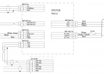
WMMT Namco FFB Wiring.png

Specifically I'd love if someone who has one of these could tell me the behavior of the LEDs on the board.

As it is, when powered on I get a Red LED solid on, and a flashing green right next to it. There are 2 other LEDs on the board that I'm not seeing light up, though I haven't had a chance to look at them when I think the game is sending a command.

With an RS-232 adapter on my computer, I tried sniffing the communication between the Chihiro and the board, and I see one command sent from the Chihiro and nothing sent back from the board.

I have checked and double checked the communication wiring between Chihiro and this board. Ground to Ground, RXD to TXD, and TXD to RXD.

I don't get any activity in my motor, either. It's a 90VDC motor and I verified it works fine by directly applying 12v to it.

What does work? This board gets the steering pot wired directly to it and passes through the voltage to the analogue input in the JVS i/o. This is working fine. The game registers wheel movement perfectly when passed through this Namco board.

Any help is appreciated.
 
That won't work. Each board has its own ForceFeedback. ONly Ringedge and Lindbergh share the same one. so it's normal you get no answer from Force Feedback (FFB) Board

If what you have is an outrun2 for Chihiro, you need this board:
http://s380.photobucket.com/user/glstar3/media/Chihiro/ChihiroKIT_2.jpg.html
Maximum Tune is on Chihiro but seems to use a special Namco forcefeedback card (as winteriscoming has shown).
I'm interested too, I'd like to run WMMT on my OR2 cab with FFB.
 
Last edited:
That won't work. Each board has its own ForceFeedback. ONly Ringedge and Lindbergh share the same one. so it's normal you get no answer from Force Feedback (FFB) Board

If what you have is an outrun2 for Chihiro, you need this board:
http://s380.photobucket.com/user/glstar3/media/Chihiro/ChihiroKIT_2.jpg.html
Maximum Tune is on Chihiro but seems to use a special Namco forcefeedback card (as winteriscoming has shown).I'm interested too, I'd like to run WMMT on my OR2 cab with FFB.
each of these two games use different I/O and FFB board.
 
OK, so my board is supposed to be for Max Tune. Why would it not work for Max Tune when I netboot it?

The chip on the FFB board says "WMM 1".

I'm not trying to use the NAMCO board for OR2SP. I'm trying to use the NAMCO board for netbooted WMMT (1 or 2).
 
Does this board maybe need a 232 to 422 adapter or the other way around? I forget which serial type Chihiro uses but Sega seemed to go back and forth throughout the years. I believe some hardware models also had jumper settings to change the port protocol (again unsure of Chihiro is one of them).

I don't understand why they changed around the protocols for FFB for every friggin game. The Happ standard is so straight forward and simple it's a shame not everyone uses it (it's just 5 pins, 1 bit for direction followed by 4 bits for intensity).
The wiring diagram doesn't indicate that there's an adapter in between. The same header from the Chihiro is already putting out RS-232 for the card reader unit. I traced the signal wires on the NAMCO FFB and they go to a RS232 to CMOS converter, so I have no doubt the board needs RS232. I can't say for sure the Chihiro is outputting RS232, but the wiring is consistent with RS232, not RS422.
 
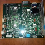
Here's a pic of my Namco board:
IMG_20160505_090045.jpg

My assumption is that if the board is tied to one game, it's due to the rom chip. There's an empty socket and a jumper that I think may let you drop in a different rom. My rom is labeled as WMM1 STR-0B (B was hand written over a printed A, so it used to say STR-0A).

I can't find any documentation on this board. I'm not even sure what the board is called. On a printed label it says "V315 STR PCB 2600960100".

There's a jumper and a set of 4 dip switches.

Here's a picture of a Namco board someone listed on a forum:
spares-Maximum-Tune-123-Drive-board.jpg


They listed is as being for Maximum Tune 1/2/3. The label says "WMM 2 STR-OA".

The same person listed this Namco board for Mario Kart, which says "MKA 3 STR0A":
spares-Mario-Kart-steering-pcb.jpg


At any rate. I'd love to just get my board working with whichever version of WMMT it's supposed to work with. Ultimately I want to figure out the protocol and try to make a translator so that WMMT can work with Sega FFB.
 
Last edited:
each of these two games use different I/O
Not to argue, but just for the sake of documenting what I'm seeing, both WMMT 1 and 2 that I'm netbooting can work fine on Sega version 1 JVS I/O and have the same pinouts on both. I figured out the wiring for the 6 position (2 switches and 2 optos) WMMT shifter to the Sega I/O, and the shifter works in both games without changing the wiring.
 
The wiring seems pretty straight forward. I'm assuming you checked that FFB is enabled in the game test menu? Is it possible you got a bad board?
 
I believe some hardware models also had jumper settings to change the port protocol (again unsure of Chihiro is one of them).
If anyone has information on this, I'd appreciate it. I took off the media board since I knew there were jumpers underneath it, but the particular pins used for communicating with this Namco board weren't connected to any of the center jumper pins.

I was very interested to find that they go to an unpopulated jumper (as in just holes, no pins even) that would allow the signals from these pins to go to an unpopulated 9-pin D-sub serial port. Where TXD and RXD would have ended up at the correct pins on the port.

I think I'd have to take the base apart a lot more to investigate where these two pins come from/go to. I don't think I want to go through that if I don't have to.
 
Last edited:
The wiring seems pretty straight forward. I'm assuming you checked that FFB is enabled in the game test menu? Is it possible you got a bad board?
Yeah, it's enabled. Unfortunately these games don't have a steering test in the test menu. It tries to initialize at boot, giving a wheel error. It does the same thing if no board is plugged up at all.

It's entirely possible I got a bad board, but I have no way of knowing how it's supposed to behave to be able to come to that conclusion.

I would think, even if I had the board wired up to the wrong game that still uses Namco FFB, there would be some kind of communication back and forth to establish that it was the wrong board and error out. As it is, I see the Chihiro send out 1 command (not sure if I've got my port setting correct to know if I'm seeing the actual command or just garbage) and nothing coming back. It doesn't even try multiple times.
 
The manual for this thing is super not-helpful. Every steering motor error is either "make sure it's plugged in" (despite the fact they don't even specify how it should be plugged in) or "replace the motor board". Thanks NAMCO!

Just spit-balling now, fuses are good? Are you testing this with everything connected? Maybe there's a load sensor that deactivates the board when there's no motor or high voltage supply attached...

I think at this point I'd just be taking some shots in the dark... reversing Tx an Rx to see if that does anything, try hooking it up to the Tx and Rx pins for the card reader to see if you can at least elicit a response. maybe hook up to your pc and try some random commands.

There are a few of people on KLOV listed as having dedicated cabs:
http://www.arcade-museum.com/members/game_census.php?klov_id=13307
http://www.arcade-museum.com/members/game_census.php?klov_id=18862
http://www.arcade-museum.com/members/game_census.php?klov_id=13556
http://www.arcade-museum.com/members/game_census.php?klov_id=13741

maybe send them all a PM to see if they can confirm the wiring and give some insight as to what the LEDs are supposed to be doing. Or if you're willing see if any of them would be willing to test your board for you.
 
reversing Tx an Rx to see if that does anything
Done that. :P
maybe hook up to your pc and try some random commands.
Done that. :P

try hooking it up to the Tx and Rx pins for the card reader
Haven't tried that, but assume it would result immediately in a card r/w error since it doesn't get the response it wants back, and lock up the game (just from my experience with card r/w communication).

I even found another set of RX/TX on the board and wired to that to no avail.

Are you testing this with everything connected?
I've tried with everything connected. The only thing I'm unsure of is the 8-pin connector on the board. They've got a wire going to a pin called FREE. They have that going to a pin on the NAMCO I/O simply labeled POWER. I measure 5v coming off of the pin on the FFB. I'm not sure what to do with it. Maybe it needs to go to an input on the I/O to indicate that there's a FFB board present?


fuses are good?
Forgot to answer this one. Yes, they check out. :)
 
Last edited:
Can't say I know your exact issue, but the same board, albeit badged as V257 STR PCB is used on RRV and Wangan Midnight/Wangan Midnight R on the 246.
From my memory (I don't have to use it anymore thankfully with the hacks...) it connects to RS232 via the 3-pin header on the 246 PCB, not the RS-422 JVS, so you should be good there, although iirc, it's wired in crossover...?

Another thing to look into is that namco released numerous iterations of the same pcb's for driving, shooting, and general IO.. but most of the time, they dropped a custom rom chip into each one to identify to the proper game it was to go with- does the code on the flashrom on yours match the game you're trying to run- if not, this may be part of the reason..

If you're not seeing more than a single command being issued, you might want to swap your tx/rx lines and see if that helps.
Alternately, if the board's not specifically the one for your game- if it is powered up and running some kind of incompatible firmware, it COULD simply ignore communication unless it's at the right bitrate and/or the proper init bytes are sent.

Sadly, there's really poor documentation on the IO pcb's out there.

Just some thoughts.
 
I've tried with everything connected. The only thing I'm unsure of is the 8-pin connector on the board. They've got a wire going to a pin called FREE. They have that going to a pin on the NAMCO I/O simply labeled POWER. I measure 5v coming off of the pin on the FFB. I'm not sure what to do with it. Maybe it needs to go to an input on the I/O to indicate that there's a FFB board present?
that's an interesting theory... looking at the schematic that pin uses a blue wire and there's a blue wire labeled "Power" on the FCA board connector...

does that "FREE" pin trace out to any logic circuits or does it just run into the 5V lines on the board?
 
does that "FREE" pin trace out to any logic circuits or does it just run into the 5V lines on the board?
It looks like it's not tied to the 5V line coming in on the board. I'm seeing the trace split across a couple of ICs, through some resistors and a capacitor, so not sure where it originates.

I'm not sure how this could wire into the Sega JVS I/O. Aren't the switches outputs that are sinking to ground? Are there any pins that accept 5V as input?
 
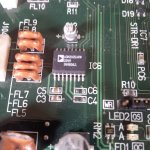
Ugh! So you know that RS232 to CMOS converter chip I referenced earlier? I'm just now seeing that 2 capacitors have been ripped out right next to it!

Luckily the data sheet for this chip is telling me what the capacitors are. I'll try to get them back in and see if that helps.

The chip is ADM202EARW.
 
I'm not sure how this could wire into the Sega JVS I/O. Aren't the switches outputs that are sinking to ground? Are there any pins that accept 5V as input?
I believe these games used the Namco FCA board for I/O : http://wiki.arcadeotaku.com/images/b/b9/FCA_PCB.jpg

Not sure if that makes a difference...

As for the Sega JVS I/O the coin meter pins Accecpt 5V as input and I suppose technically the analog pins but thats all I think and neither are relevant to this situation. I'm unsure if the FCA board is any different in this regard.
 
So here's the damage. C6 and C4 are missing, with a little bit of trace damage. I can't fathom why these would have been pulled out. It's possible the board was dropped or something, but don't know how only 2 little capacitors would get knocked out when there are components much taller nearby that seem fine, except that component to the very bottom left of the picture. It looks like it might have had a chip off the top. It's labeled FL4 and I believe it's tied to 12v power coming in.

IMG_20160505_110632.jpg

Here's the schematic for the chip that says I need .1uf capacitors.
ADM202E schematic.png
 
Back
Top