What's new

LittleLarrySellers

Professional
Joined
May 27, 2019
Messages
446
Reaction score
529
Location
Whitehall, PA
Well, this is my first major fail in the hobby. So I picked up a dead GnG board for cheap on eBay. I wouldn't mind a backup to my working board and figured it could be fun to try and fix.

The board had some of the ROMs missing and the PROM and someone absconded with the sound amp (HA13001). Otherwise, was just some corrosion on the solder sides.

When the board arrived I cleaned up the corrosion and then tried moving my ROMs/PROM from my working board to the dead one and see what happens. To my surprise, the board powered on and I was able to coin up! There are some sprite issues with Arthur and the joystick UP wasn't registering and obviously no sound. Otherwise, huge progress from DOA!

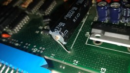
I put aside the joystick and sprite issues to tackle the sound first. I ordered a HA13001 and soldered it on and bingo I had sound. I noticed though the sound of Arthur's weapon and the impact noise on tombstones was missing. I couldn't decipher anything from the schematics for the sound section so I looked at the caps and noticed the big axial one in the sound area seemed to have started to leak as you can see in the pic.

Here is where EVERYTHING went to shit.

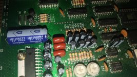
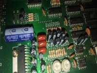
I ordered a 2200uf 25V cap to replace it b/c my understanding is the voltage is just an upper bound and should be ok to use higher rated ones (right?). After I soldered it in (polarity was correct) the board died. Like it is totally fubar now. I can't get stable power to the board. My minigun would usually display the 5V on the voltmeter and the green light would be on my PSU (RT-65A). Now, there is no 5V reading and my power supply has no green light and just makes a clicking noise. I assume short circuit security protection kicking in. Somehow after replacing that one cap the board seems to have shorted so I can't even get it to power on :(

Here is what I have done with no success:
  1. I have tried doing a shotgun replacement of all the other caps.
  2. I have verified if I just send 12V the board will power on stably, so it is 5V.
  3. I have removed the bottom board and am just trying to get the main PCB to power on.
  4. I even replaced the 2200uf 25V with a 16V cap like it originally had just in case that somehow did it.
  5. I desoldered the HA13001 and tried in case that was the culprit and then soldered back, either way fubar.

Basically, I had a board that was on the road to working and is now a giant 35 year old paperweight. FML. I don't know how replacing that one cap caused the board to crap out. Can I create a short to ground from the via? I have recapped stuff before and never had an issue like this.

I also don't know how to debug this further now. I read something about cutting traces which you can't do with GnG and not sure I even would if I could. I also saw some YouTube videos about using diode mode on my working board vs. the dead board chip by chip, pin by pin find where the resistance drops substantially as a way to find the culprit. Is this the best approach? Any other suggestions would be appreciated. Really bummed by this turn of events.
 

Attachments

  • gng.jpg
    gng.jpg
    772 KB · Views: 298
Sounds like there is a short to ground somewhere. I'd get the multimeter out and start probing around the areas you worked on. Look for shorts to ground from the point of the cap replacement and build a radius out from there. Start at the source, then work outwards.

Dumb question but you did test the supply and gun on a known working board right? Way small chance but test to make sure your power supply didn't just die at a really inopportune moment. I reread what you wrote and you didnt say "tried supply and supergun on known working board and tested fine"

Based on the photo I don't see any real corrosion from the cap
 
Last edited:
Yes, the supergun and power supply are fine. I actually took my working GnG board and verified it will power on stable with just the top board.

When you say probing with the multimeter, you mean doing that diode test? And comparing against my good board? Is that how you find the short? Sorry I'm still learning as I go so my questions may be lame.
 
Not exactly. If there is a short to ground, a non-ground point will have continuity to the ground plane.

Think of it this way. If you put one probe of your multimeter on ground on the JAMMA edge, and the other probe on any ground contact on the pcb itself, in continuity mode it will have a sustained beep.

If you put one probe on the JAMMA edge ground, and another on the JAMMA edge 5V, you won’t have continuity and you won’t hear a sustained beep.

If I was diagnosing it, I’d alligator clamp a ground point (board edge if ground plane is exposed / JAMMA edge) and then alligator clamp the other end to my probe.

I’d then use the second probe to check everywhere I worked before the problem occurred.

If you have ground on both ends of something like a cap, you’d have a short to ground in this instance.

That’s how I’d check for a short to start. I’d check the components near where you were working before the problem occurred, and see if anything was shorted. You might not find anything, but that rules out issues and is still useful

I’d check the via hole where the cap leaked first. It’s possible electrolytic fluid made its way inside and corroded the planes. But that’s just a theory as I don’t know if that’s what occurred. It’s possible some corrosion grounded something out and your solder bridged the planes and caused the ground. I’d bet against this but hey...always good to think of all the angles right?

ive never seen a GnG board in person. Is their a fuse anywhere?
 
also in your photo something seems to be sticking up in the back of the via. Is there anything lifted that isn’t just solder? It’s so hard to tell from the photo but something looks a tad bit off there
 
Ah nice. That is a good way to do bunch of continuity checks with the alligator clamp. I can try probing around quickly with that approach. No fuse on the board either btw.


The photo was a pic of the original "bad" cap which lead me into this mess after I replaced it. Here is a better photo with all the caps I replaced and the HA13001 I soldered in which originally got me most of the sound back before this thing shorted out.

Thanks for the tips. Will try the alligator probing first.
 

Attachments

  • gng_caps.jpg
    gng_caps.jpg
    131.8 KB · Views: 135
This will be my first post lol, and I am not an arcade expert-in fact I am still learning. But I do know electronics. It may be the angle of the picture, but it looks like there's some solder on your 13001 connecting to points (circled in the pic below). Again, I don't know much about this stuff yet, but I saw this and wanted to give some input.
 

Attachments

  • BOARD.jpg
    BOARD.jpg
    111 KB · Views: 146
welcome aboard! I will check tonight but I did already go over the pcb looking for any accidental solder bridging. I could have missing something. Thanks for the input.
 
Ah nice. That is a good way to do bunch of continuity checks with the alligator clamp. I can try probing around quickly with that approach. No fuse on the board either btw.


The photo was a pic of the original "bad" cap which lead me into this mess after I replaced it. Here is a better photo with all the caps I replaced and the HA13001 I soldered in which originally got me most of the sound back before this thing shorted out.

Thanks for the tips. Will try the alligator probing first.
If no fuse then yes something seems grounded out, or bridged. Just go over all your work and test everything. You should be able to pull the schematic for the chip as well...you can test pins against each other to make sure you didn't bridge two pins inadvertently. Hard to say from your photo if you did but its worth checking. Good luck getting it working again!
 
Yeah, I have the schematics. I will go over everything with a fine toothed probe LOL. Hopefully, I find whatever it is I f'd up. Thanks!
 
Yeah, I have the schematics. I will go over everything with a fine toothed probe LOL. Hopefully, I find whatever it is I f'd up. Thanks!
You'll find it eventually. Although I'd be 99% confident something you did caused the problem, def still look over the entire board. Its uncommon but not unheard of for something ELSE to eat shit and die at a very inopportune time. I've definitely tried to figure out "what I did wrong" before, only to come to the conclusion something else COMPLETELY different stopped working at an inconvenient time and fooled me into fault finding an issue that didnt exist

Basically, don't rule anything out until you've ruled it out with testing! lol
 
To me the legs of the 2200uf capacitor are making a short, it doesn't look clean to me. How have you pulled the old one? Did you need to clear the holes before installing the replacement part? If so how did you proceed?

You could also use a milliohmeter to find the point of least resistance.
 
I used my desoldering gun. Don't recall any issue. I applied some fresh solder and then hit it with the gun and pulled the old cap out and put the new one in and soldered it. I usually have the board sideways and gently hold the cap and desolder from the other side and unless it is being a pain in the ass it will slide out after I hit both holes.

Just so I can learn to spot things better, what doesn't look clean here. I obviously don't see it :O
 
If you put one probe on the JAMMA edge ground, and another on the JAMMA edge 5V, you won’t have continuity and you won’t hear a sustained beep.
So interestingly I actually do hear a sustained beep on the GnG board between ground and 5V on the "Capcom classic" edge. I thought I found an issue but then I tried the same test on my working board and it also beeps on GND to 5V continuity test!?

Then I saw it was registering a small resistance on the multimeter. I checked the specification for mine (Fluke 117) and I read it beeps if less than 250 Ohms of resistance. I see the GnG one has like 40 between GND and 5V. I checked one of my CPS1 boards and there I see like 350 for resistance on JAMMA edge between ground and 5V and thus it doesn't beep.

Is this normal? I assume it is since my working GnG board has the same readings as the fubar one.

I guess I will have to do more than listen for a beep when checking continuity on this board specifically.
 
Yes, seems normal if it’s identical on your working board. Sometimes continuity testing and resistance is tricky.

The more I look at the first photo the more I see that raised area behind the cap leg. It looks like something is lifted.

I don’t have a schematic or this game, but look into seeing if can safely test it with the cap removed. See if it gets power.
 
So interestingly I actually do hear a sustained beep on the GnG board between ground and 5V on the "Capcom classic" edge. I thought I found an issue but then I tried the same test on my working board and it also beeps on GND to 5V continuity test!?
Then I saw it was registering a small resistance on the multimeter. I checked the specification for mine (Fluke 117) and I read it beeps if less than 250 Ohms of resistance. I see the GnG one has like 40 between GND and 5V. I checked one of my CPS1 boards and there I see like 350 for resistance on JAMMA edge between ground and 5V and thus it doesn't beep.

Is this normal? I assume it is since my working GnG board has the same readings as the fubar one.

I guess I will have to do more than listen for a beep when checking continuity on this board specifically.
Weird, I also have a Fluke meter and it beeps for continuity below 20 ohms.
Problem with those copper masked board is one side is the ground plane, the other side is +5V IIRC. Meaning if you damaged the via or pulled it by only half a millimetre you could very well end up with a short between ground and +5V.
 
Problem with those copper masked board is one side is the ground plane, the other side is +5V IIRC.
Found it! Desoldering fail on my part. On the solder side I guess I was a bit aggressive and I burned off some of the green mask around the via when removing the old cap. After you said this I went back and double checked and I was actually getting ZERO resistance between ground and 5V on the failing board. The working board had resistance even though both beep in continuity testing.

I desoldered the cap again and saw that once the solder was gone I had resistance between 5V and ground so looks like when I soldered it in I was bridging the leg with ground plane on the area around the via.


Anyway, thanks guys for all the advice. At least the board boots now and is not totally fubar only slightly fubar :) Hopefully I can work toward actually fixing it now instead of making it worse.
 
So there was a problem with the via in the photo! Glad you found it :)
 
Back
Top