Hey.
I ordered a cheap Neo Geo one slot motherboard off of AliExpress. Plus some other electronic supplies to consolize it.
I did some padhacking before, made some arcade sticks. So I know a little about electronics, but the more I research this the more complicated it gets..
I did a lot of digging online and I think I get it. But I'm going to write down my conclusions on how to do it here.
Hopefully someone with experience is willing to look it over and tell me if I'm making a mistake/doing something stupid.
Maybe this'll even serve as a tutorial for other beginners if I get it right. If I'm corrected I will edit my original post to reflect the advice given (let me say this so it doesn't look weird when they correct me on stuff I already did).
I think my motherboard is a mv-1f, but all the mods look similar. Just different places to solder onto the motherboard.
Since I don't have a supergun to test it with I'll start with a 5V mod. So I can use a cheap simple 2A 5V phone charger to be my power supply. I've seen people use fuses... but I'm going to assume such a small power supply isn't going to fry my board. If there are resetting issues, I'll get a 3A charger if they underreport the actual output.
I ordered some 56 pin Jamma edge connectors. Using this pinout
https://www.aussiearcade.com/forum/...mvs-jamma-harness-adapter?p=949311#post949311
I'll add theb +5V to the +5V pin (3 and C). I'll do a connectivity test to see if all the ground pins are connected and place also two connections to ground from my phone charger on 1 and A.
I got two male db15 cables, four db15 female sockets. I will use those on seperate arcade sticks with sanwa parts. I'll make my own pinout for the joystick and buttons and wire them to the female sockets accordingly. So I can still actually disconnect my controllers.
Youtuber GagdetUK164 made a video showing how he hooked up the RGB and Sync wires to a european Scart plug.
He copied his supergun. I'm going to assume pins 12, N, 13 and P contain outgoing signals. All the ground pins from the Scart connector I will combine and plug into pin 14. The R G and B signals will have a 390 ohm resistor each. A 470 ohm resistor for the sync signal. The +5 signal I will also have a extra wire from the +5 pins going one extra to the 5V scart plug going through a 47- ohm resistor as GadgetUK164 did. The 12+ plug I will leave alone since I applied the 5V mod.
The basic stereomod for all the one slot boards require the same electronics, but just have the A,B and C pins on the board in different locations. This is a schematic for the basic version. It will give you stereo sound which will work fine on your tv. But be kind of quiet.. The Jamma nation website with tutorials showing where A B and C pins are is down at the moment, but I'm sure it'll be back online soon.

If you want to bring it up to line level and be more in line with other devices hooked up to your tv. You need the MLK amplified circuit.
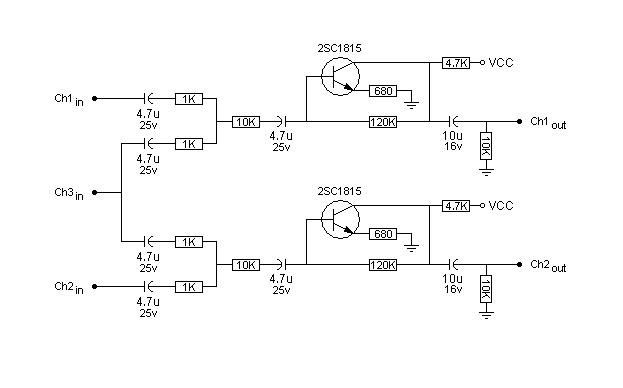
I'm assuming Ch1 is the same as A,Ch2 is he same as B and Ch3 is the same as C. Plus that VCC is also a +5V source. I'll take the other +5v pin and have 2 wires going to it. One from the charger and the other to these +5V entry points in this diagram.
I'll leave the wires from the power supply and scart out hanging on the back of the box I'll make for it, making sure you can't pull on the wire to pull connections off. But not with a special connector plug.
A new bios rom chip already arrived. I think on the MF1Z you just swap out the rom chip. But on a few you need to remove the chip and add in wires to the socket. I have no found a actual pinout for that process... Should be finicky to solder the wires onto the small feet. But doing connectivity tests to see if I am not briding and that the wire is actually connected to the pin should help a lot.
That covers the power supply, the controls, video output and soundoutput.. That seems to be it. If anyone knows if I'm making a mistake here, or knows a better practice for doing it... I'll greatly aopreciate it.
I ordered a cheap Neo Geo one slot motherboard off of AliExpress. Plus some other electronic supplies to consolize it.
I did some padhacking before, made some arcade sticks. So I know a little about electronics, but the more I research this the more complicated it gets..
I did a lot of digging online and I think I get it. But I'm going to write down my conclusions on how to do it here.
Hopefully someone with experience is willing to look it over and tell me if I'm making a mistake/doing something stupid.
Maybe this'll even serve as a tutorial for other beginners if I get it right. If I'm corrected I will edit my original post to reflect the advice given (let me say this so it doesn't look weird when they correct me on stuff I already did).
I think my motherboard is a mv-1f, but all the mods look similar. Just different places to solder onto the motherboard.
Since I don't have a supergun to test it with I'll start with a 5V mod. So I can use a cheap simple 2A 5V phone charger to be my power supply. I've seen people use fuses... but I'm going to assume such a small power supply isn't going to fry my board. If there are resetting issues, I'll get a 3A charger if they underreport the actual output.
I ordered some 56 pin Jamma edge connectors. Using this pinout
https://www.aussiearcade.com/forum/...mvs-jamma-harness-adapter?p=949311#post949311
I'll add theb +5V to the +5V pin (3 and C). I'll do a connectivity test to see if all the ground pins are connected and place also two connections to ground from my phone charger on 1 and A.
I got two male db15 cables, four db15 female sockets. I will use those on seperate arcade sticks with sanwa parts. I'll make my own pinout for the joystick and buttons and wire them to the female sockets accordingly. So I can still actually disconnect my controllers.
Youtuber GagdetUK164 made a video showing how he hooked up the RGB and Sync wires to a european Scart plug.
The basic stereomod for all the one slot boards require the same electronics, but just have the A,B and C pins on the board in different locations. This is a schematic for the basic version. It will give you stereo sound which will work fine on your tv. But be kind of quiet.. The Jamma nation website with tutorials showing where A B and C pins are is down at the moment, but I'm sure it'll be back online soon.
If you want to bring it up to line level and be more in line with other devices hooked up to your tv. You need the MLK amplified circuit.
I'm assuming Ch1 is the same as A,Ch2 is he same as B and Ch3 is the same as C. Plus that VCC is also a +5V source. I'll take the other +5v pin and have 2 wires going to it. One from the charger and the other to these +5V entry points in this diagram.
I'll leave the wires from the power supply and scart out hanging on the back of the box I'll make for it, making sure you can't pull on the wire to pull connections off. But not with a special connector plug.
A new bios rom chip already arrived. I think on the MF1Z you just swap out the rom chip. But on a few you need to remove the chip and add in wires to the socket. I have no found a actual pinout for that process... Should be finicky to solder the wires onto the small feet. But doing connectivity tests to see if I am not briding and that the wire is actually connected to the pin should help a lot.
That covers the power supply, the controls, video output and soundoutput.. That seems to be it. If anyone knows if I'm making a mistake here, or knows a better practice for doing it... I'll greatly aopreciate it.
