What's new
You could make a voltage divider out of resistors. See here:

https://learn.sparkfun.com/tutorials/voltage-dividers

However, personally I wouldn't, as per this:

Application Dont’s
As tempting as it may be to use a voltage divider to step down, say, a 12V power supply to 5V, voltage dividers should not be used to supply power to a load.
Any current that the load requires is also going to have to run through R1[/sub]. The current and voltage across R[sub]1 produce power, which is dissipated in the form of heat. If that power exceeds the rating of the resistor (usually between ⅛W and 1W), the heat begins to become a major problem, potentially melting the poor resistor.
That doesn’t even mention how inefficient a voltage-divider-power-supply would be. Basically, don’t use a voltage divider as a voltage supply for anything that requires even a modest amount of power. If you need to drop down a voltage to use it as a power supply, look into voltage regulators or switching supplies.
 
After reading a bit, you're definitely right that it's dangerous to use resistors for dropping voltage with high power sources like PSUs.

I found what may be the perfect option though. Creative INSPIRE speakers took 13.5V AC (5A), and their PSU is cheap on eBay. It's model US-1450. Even though the PSU isn't labeled as AC output, I verified in a few different sources that it is in fact AC (not DC like most PSUs). I got one for $13/shipped. I can't test it out until I move home in a few years though.
6a82173a1dcab33d90927c1fca6839df.jpg
I put a bid on one ending in a few days. Will post success/failure whenever it comes in.
 
Anyone have a spare Q-Sound amp PCB? I have a transformer that needs a partner.
 
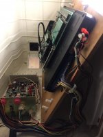
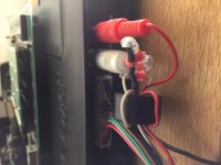
I have a Capcom Impress and I do know that when I used a non CPSII board with it that had a stereo output, the amp wouldn't work unless I switched the patch cable from the loom back over from the stereo output to the mono output, so that the audio came from the Jamma edge. Note the left channel has two cables to the right channel's one. Also note my super shitty patch job when I bust the cable recently.

I also recently ordered one of the Q-Sound amps from eBay that matches the one in my cabinet, so I'd have a spare. Its not arrived yet, but if I can help at all, let me know


.
IMG_5129.JPG
IMG_5132.JPG
 

Attachments

  • IMG_5131.JPG
    IMG_5131.JPG
    500.2 KB · Views: 407
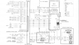
  • impress.png
    impress.png
    838 KB · Views: 424
Last edited:
Have you tried plugging a set of working RCA cables straight from the output of the CPS2 to the input connectors on the amp, bypassing all of the other connectors in between?

Personally, I would wait for the other amp, because if that isn't working either, you can rule out the amp and then focus your efforts on the wiring.

EDIT: according to the pics and the wiring schematic, power for the amp is just taken from 12VDC pin on the jamma connector. No need for a transformer, guys!
 
Last edited:
Oh no, not this again. Forget everything you read online or in schematics, it's 13.5V AC.
 
Oh no, not this again. Forget everything you read online or in schematics, it's 13.5V AC.
I'm sure that works as well, but have you tried 12VDC? Because that's how it is in an Impress and it works. There's no separate transformer.
 
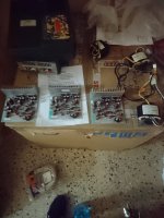
I have lots of those amplifier, 2 are alredy in capcom impress and 3 with theyr transformers.

The ones in capcom impress cab have just a 12v wire from psu and work perfect with cps2 by using a good shielded stereo ac cable directly from amp to te cps2 A board, but it makes noise if connected to a CPS3 or CPS1.5 due to the ground loop.
The original rca cable inside the capcom impress does not go, inexplicably a channel does not have the gnd ..so to work at least with cps2 the best way is simply bypass the original one cable with a one shieded.

The ones wich come with dedicated 18v toroidal transformer just need 12vAC with 2,5Amp minimum, this amplifier not have ground loop and work perfect with all cps q sound game boards.

about 10 years ago I built a 12vAC 2.5amp (dual 12v, 12v-0-12v) transformer that powered this type of amplifier and I could use it in other cabinets, this trasformer with 230v imput is now lost and I'm trying to figure out how to mount one of these amplifiers in my capcom impress.

Also the original capcom-kitamura toroidal transformer must receive exsactly 100v or 120v(grey wire) ac otherwise sometimes not work...in eu with stepdown we have about 110 and it is not good…

So I have some questions
1) why capcom has put an amplifier that does not work perfectly inside his Impress cab?
maybe I'm wrong but in two cabinets the situation is identical
2) How to put easily and safely one q sound amp earlier version with tranformer inside the Impress and where to wire the ac imput for the "18v" transformer.
 
Last edited:
Oh no, not this again. Forget everything you read online or in schematics, it's 13.5V AC.
I'm sure that works as well, but have you tried 12VDC? Because that's how it is in an Impress and it works. There's no separate transformer.
Yeah, I tried 12V DC and it didn't power on. It's definitely 12-13.5V AC.
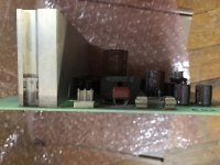
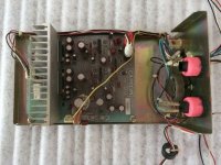
If you look at @tate&yoko 's amp it has an additional coil on the board by the input voltage and is missing a D3SBA20 Bridge Rectifier. Amps like the the ones used in US Big Blue and Q25 cabinets do not have this and use the Kitamura Transformer and a D3SBA20 Bridge Rectifier. Here is a pic of my spare, which requires the AC transformer. As you can see no coil, but there is a Rectifier.

[align=center]Qsound with separate Transformer.jpg


Here is one out of an Impress:
Impress QSound.jpg[/align]
Sadly it seems they still used the same part #s even though its clearly a revision to the board.

@SmokeMonster you found this out back in 2016 btw, on the first page even.
 
Last edited:
Mystery solved!

After I saw this, I ran and grabbed a Q-sound amp PCB that I got from a EU eBay seller. I think the guy bought all of Yaton's stock because Yaton pull his listings. Yaton said someone bought all of his remaining stock when I messaged him about them. That guy probably couldn't use them for his purposes for the reasons you mentioned and started dumping them on eBay.

Sweating bullets, I grabbed my PCB to see if it had the coil or the rectifier. I need it to go into a US Big Blue that has all of the rest of the Q-sound parts. It has the rectifier. So I am set (once I get around to that project).
 
I have two capcom impress but also lots of these amps with transformers and yes I see there are diffrence the one with coil is 12Vdc and the one with rectifier require the tranformer 18vAC (this mean that suply about 12-13v). but why CPS3 get noise from the ones with coil is relly a mistery because it is impossible that capcom release these amps with this issue.

Now I will replace the original capcom impress with the Q25 ones, first I need a good step down tranformer for japan application (230vto100v) because the capcom toroidal tranformer will not supply the correct voltage if you do not have exsacrtly 100v (black wire) or 120v (grey wire).
 

Attachments

  • DSC_0495.jpg
    DSC_0495.jpg
    179.5 KB · Views: 271
I have two capcom impress but also lots of these amps with transformers and yes I see there are diffrence the one with coil is 12Vdc and the one with rectifier require the tranformer 18vAC (this mean that suply about 12-13v). but why CPS3 get noise from the ones with coil is relly a mistery because it is impossible that capcom release these amps with this issue.

Now I will replace the original capcom impress with the Q25 ones, first I need a good step down tranformer for japan application (230vto100v) because the capcom toroidal tranformer will not supply the correct voltage if you do not have exsacrtly 100v (black wire) or 120v (grey wire).
My only theory on this is primarily the differences between CPS2 and CPS3 audio sections.

CPS2 line level has less interference using its BGS Vol control Vs CPS3 even on line lvl outputs goes through that horrible volume pot. Having it hooked up for QSound in my Q25 and tapping that pot gets static on the amp.
 
maybe the issue is inside the cps3 amplifier chip, Toshiba TA8201AK and in six pin.


I can confirm, no ground loop or humm with the Q25 amp.

I have connected the cps3 board to my sony 7.2 (str-DN1060) sintoamp and get ground loop (humm noise), cps2 not have this issue, also consider I tested not one but eight cps3 motherboards (from cyclone to rev4) with same results
 
Last edited:
T'was sitting in front of us for almost the last 3 years. Oh well, I am sure we have done less than intelligent things before (like pre-ordering the Playstation Mini Classic).
 
T'was sitting in front of us for almost the last 3 years. Oh well, I am sure we have done less than intelligent things before (like pre-ordering the Playstation Mini Classic).
Thankfully I didn't do that one, ha.

Need to hunt down a transformer though for sure.
 
Back
Top