@rewrite can you send me a link to the guide? Tried searching for it and couldn’t find it.
http://arcadecontrols.com/BBBB/acwiring.html
The Bob Roberts AC Wiring guide.
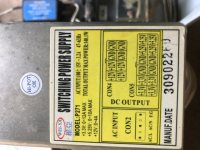
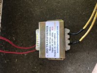
Don't know. Does the chassis you ordered and installed require 100v?Also, I’ll need to order one that outputs 100V, correct?