What's new

tamfab

Beginner
Joined
Jun 12, 2020
Messages
23
Reaction score
5
Location
Hungary
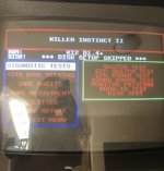
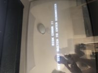
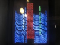
Having some disk error problems running ki2 on my k1 board.

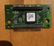
I’ve got the proper ki2 bootrom for the conversion and also for allowing cf card and others to boot not requiring original hdd as well as the ki1 upgrade board.

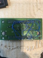
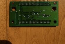
I keep getting disk errors. I’ve checked the upgrade board too and fixed the missing pin connections, now I have continuity on all pins.(see pic below)
Does anyone have an idea of what I can do to fix this...especially experience with the upgrade board on what else I should check.

Ki1 obviously works fine.

please see the attached pictures...
 

Attachments

  • F55DC58B-8A8E-4E7E-BBC9-BA57C3B0158F.jpeg
    F55DC58B-8A8E-4E7E-BBC9-BA57C3B0158F.jpeg
    33.4 KB · Views: 119
  • A0E6D4C4-4E46-479A-9C94-D7848BF976D1.jpeg
    A0E6D4C4-4E46-479A-9C94-D7848BF976D1.jpeg
    25.9 KB · Views: 109
  • FC34D369-1A00-44A7-837E-8D573270E04E.jpeg
    FC34D369-1A00-44A7-837E-8D573270E04E.jpeg
    29.9 KB · Views: 117
  • B7557646-39C3-440B-A26A-B586C408C30F.jpeg
    B7557646-39C3-440B-A26A-B586C408C30F.jpeg
    16.4 KB · Views: 165
  • 6BD8B053-ECBC-4C30-BB2E-7B1D1F22E090.jpeg
    6BD8B053-ECBC-4C30-BB2E-7B1D1F22E090.jpeg
    38.6 KB · Views: 127
  • 662EBD1D-8634-41BB-8AC7-B20F2BD0DAC8.jpeg
    662EBD1D-8634-41BB-8AC7-B20F2BD0DAC8.jpeg
    25.8 KB · Views: 126
  • B511D583-8C89-40C9-B69A-452EB8170BB3.jpeg
    B511D583-8C89-40C9-B69A-452EB8170BB3.jpeg
    27.7 KB · Views: 135
Did you just connect the input pins to the output pins? That would bypass the entire rest of the pcb. The original board sends some of the input signals to their output pins, indirectly. Your images are too small for me to see clearly (try using imgur.com or another host) but the first thing I'd suggest is removing all those jumper wires.
 
Last edited:
I did bypass the 6 non working pins...I had the same screen come up before I did the bypass and unfortunately after as well
 
Let me know which 6 pins and I’ll trace them on my board for you if I can. But I don’t think they’re supposed to be directly wired to the other side.

There’s not much to check on the board otherwise. Cold solder joint on one of the connectors. Missing component. Cold joint on the custom chip. Could just be a bad chip too but it would be hard to diagnose.

Could you upload a higher resolution photo of both sides? Use an image host if you need, like imgur.com
 
EgnK8n3bLv1hAK0N1UX99xnTsp7mbvyrYsdfEw_VKq4kh9mz-bjv4jsb3eQ_Bgm8yTN8nmuor-rv_FVs051zoIY
idc44f.gif


Just checking, which way are you counting the pins?

edit: nevermind you're doing the first one... stay tuned
 
I was counting from the way it is labelled on the board ie. 1 and 44 labelled.
Yes according to the first pic.

Also do you have any info regarding the patched bootrom required to run ki2 on ki1 board with no upgrade card?

 
Last edited:
ruTBcqS.jpg


None of those i/o pins have direct continuity, I would recommend removing those jumper wires. Additionally I would reflow the solder on these three pins.

I have no info about that boot rom, but it would be nice if the creator released the rom, wouldn't it?!!
 
I removed the jumpers and tried reworking the above recommended pins...still no go!
So on your upgrade board those i/o points dont’s show continuity? Not even pin 44?

pretty lost now...I don’t really know where to turn...I’m considering changing the entire 2x22 idc header even...
 
right, those input pins don’t show continuity to the respective output pins. Some don’t seem connected at all (like pin 44) and others do show some resistance if I measure that, so they are at least in circuit.

I see a small scratch on one trace, above the pin that was clearly loose. I don’t think it looks deep enough to have cut it but you could make sure.

Do you have a probe or oscilloscope? I could see what pins have what activity if you see one stuck high or low or something. Or the pins on the custom U96
 
Back
Top