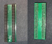
Here's a close up the soldering. The bottom solder may be an issue here?
It's hard to tell with those through hole soldering points. But, if you used flux it should have pulled the solder down and into the hole making it concave rather than convex. However it could still look like yours and be fine if enough solder was used. It took me several tries to get the soldering right. Those two points are Setup1 and Setup2 pins, that program the encryption key. So if they're faulty, it should in theory run an unencrypted ROM, but fail to write the encryption key. So... now that the bridge board is correctly seated (going to assume it's facing the right direction, hard to tell from photos) there may ALSO be a problem with the key writing, so I would again discharge EXC5 (just to be sure the keys are blank) then try an unencrypted ROM again.


")