What I mean is: Mr T Guru seems to have fixed this crackling issue with just 8 cables, which AFAIK is less expensive than a custom PCB, so if the fix with the 8 cables works perfectly, I think that should be the method used to fix the boards, instead of the custom boards, because of it being less expensive. I hope i made myself clear this time.What do you mean?So...is it confirmed that the fix developed by Mr T Guru works perfectly? with all games? if it does, I think that should be the implemented fix, as opposite to waiting for the custom boards that Darksoft will order and make him not spend more money, shouldn't it?
Thanks!!
You are using an out of date browser. It may not display this or other websites correctly.
You should upgrade or use an alternative browser.
You should upgrade or use an alternative browser.
- Thread starter joele
- Start date
Yes it works but it is not easy to do. Plus nearly 60% of all carts sold so far have been shipped to the US. Guess who would potentially have to do a bunch of those mods. Yup....you guessed it. Give me easier. I have a 60-65 hour work week at my restaurants and it's already difficult to do the arcade jobs I have coming in. I need all the help I can get.What I mean is: Mr T Guru seems to have fixed this crackling issue with just 8 cables, which AFAIK is less expensive than a custom PCB, so if the fix with the 8 cables works perfectly, I think that should be the method used to fix the boards, instead of the custom boards, because of it being less expensive. I hope i made myself clear this time.
Well, that's another implementation of what the mini PCB does, just connect 8 points to another 8 points If some feels so confident, they can do the same as Guru did...but I warn you not to try unless you can solder that kind of stuff. If you do it, at your own risk.So...is it confirmed that the fix developed by Mr T Guru works perfectly? with all games? if it does, I think that should be the implemented fix, as opposite to waiting for the custom boards that Darksoft will order and make him not spend more money, shouldn't it?
Thanks!!
Both Mitsu, Leo and Guru have been extremely helpful and I'm very grateful for their support but this was MY *cough* FIX :p
I'd rather say that it's putting 3.3V data on a 5v Data bus.The cable mod looks like it's putting 5v on the 3,3V flash rom. That could harm it on long time usage.
Pin 2 of that IC U40 or any of the 74LVC4245A indicates the direction in which data flows. In this case it's wired to GND what means that direction is always from B(3.3V) towards A(5V)
Check i.e . U34 or U38 and you'll see that they use the same chip but in this case direction pin is wired to 5V because it's used to shift down address bus from 5V to 3.3V.
Address bus goes INTO the multi flashes (already level shifted from 5V to 3V3)
Data bus goes OUT from the Flashes towards the B Board (level shifted from 3.3V to 5v)
If we remove that IC it will provide 0-3.3Vs value in the data Bus of the CPS2 and 3.3V is still in the voltage range recognized as a 1.
My apologies Darksoft, It was not my intention to take the credit for the fix from you, I only thought that it had been developed by Mr T Guru because he put the pic first. Anyway, if the board makes the work easier for you guys, then it is the way to go. I understand it perfectly.Well, that's another implementation of what the mini PCB does, just connect 8 points to another 8 points If some feels so confident, they can do the same as Guru did...but I warn you not to try unless you can solder that kind of stuff. If you do it, at your own risk.So...is it confirmed that the fix developed by Mr T Guru works perfectly? with all games? if it does, I think that should be the implemented fix, as opposite to waiting for the custom boards that Darksoft will order and make him not spend more money, shouldn't it?
Thanks!!
Both Mitsu, Leo and Guru have been extremely helpful and I'm very grateful for their support but this was MY *cough* FIX :p
Thanks for your hard work and help so far.
No worries, I was just teasing Mr. GuruMy apologies Darksoft, It was not my intention to take the credit for the fix from you, I only thought that it had been developed by Mr T Guru because he put the pic first. Anyway, if the board makes the work easier for you guys, then it is the way to go. I understand it perfectly.Both Mitsu, Leo and Guru have been extremely helpful and I'm very grateful for their support but this was MY *cough* FIX
Thanks for your hard work and help so far.
Truth is that his solution can be implemented by anyone with the skills right now.
I'm just looking for a mass production solution that is also good to be implemented by Mitsu, Guru and myself
")

It will be the size of u40 and will likely require hot air to install.Can you give us an idea on what the replacement pcb part will look like and how big it is?
Excellent news that you found the source of the issue! I bet that one was certainly frustrating to diagnose.The only solution that can be applied is changing the U40 for a new tiny custom PCB that I'm going to order today.
I'd love to see the design of the tiny PCB you're ordering and how it compares (as far as ease of installation) to doing MTG's fix.
FrizzleFried
Enthusiast
When I send Mitsu my CPS2 kit, I assume I can send the ST-V kit at the same time for the reset upgrade?
synbiosfan
Enthusiast
You'll need to send the ST-V motherboard too or do a little soldering.When I send Mitsu my CPS2 kit, I assume I can send the ST-V kit at the same time for the reset upgrade?
I forgot about that, doh.
I do the ST-V reset upgrade for $15 since it isn't a "fix" for a problem.When I send Mitsu my CPS2 kit, I assume I can send the ST-V kit at the same time for the reset upgrade?
FrizzleFried
Enthusiast
Sounds fair. I'll likely send both along to save on shipping.
hmmm yes let me make it CLEAR, I did not develop the fix, I merely implemented what Darksoft suggested as we were trying to find the problem and solution. this was tested by me and works. Darksoft did all the work, I just did a bit of soldering to double test the solution at my end.
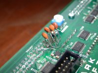
there is another fix too, a lot easier requiring soldering 8 capacitors to those connector pins and then tieing to ground.
the photo shows half of it. there are another four 470pf capacitors needed on the other side (not shown in this pic).
Again let me make this CLEAR, this is Darksoft's work, not mine, I just did the soldering on my PCB to test it here.
Please note this is really just a work-in-progress proto-type fix and is really UGLY.
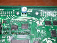
The other photo shows a cleaner version of the wiring fix. If someone is capable to solder it, this could be considered a permanent fix. You can add a drop of hot melt glue to the wires and it will stay there forever. However most 'gamers' can't do this.
You can consider these photo's just me showing off
These are not meant for the average guy.
I'm sure Darksoft will tell you if you do your own repairs you are totally on your own with regards to warranty etc. and may even refuse to accept it back for the real repair if you totally screw the PCB.
Darksofts final solution with a small board to replace the chip is clean and nice but in 99% of cases will require you to send the board in for repair to one of the authorized repairers.
I suppose he decided to do it this way because he cares about you guys and wanted to do it right
However I'm sure if you wanted to fix it yourself Darksoft will appreciate it because applying the small PCB fix will surely cost Darksoft money and the development of this CPS2 PCB and the forthcoming next run will also be costly. So if you can fix it yourself you will save Darksoft some time and money and you'll get your board working without having to wait.
Plus you might even learn something....
there is another fix too, a lot easier requiring soldering 8 capacitors to those connector pins and then tieing to ground.
the photo shows half of it. there are another four 470pf capacitors needed on the other side (not shown in this pic).
Again let me make this CLEAR, this is Darksoft's work, not mine, I just did the soldering on my PCB to test it here.
Please note this is really just a work-in-progress proto-type fix and is really UGLY.
The other photo shows a cleaner version of the wiring fix. If someone is capable to solder it, this could be considered a permanent fix. You can add a drop of hot melt glue to the wires and it will stay there forever. However most 'gamers' can't do this.
You can consider these photo's just me showing off
These are not meant for the average guy.
I'm sure Darksoft will tell you if you do your own repairs you are totally on your own with regards to warranty etc. and may even refuse to accept it back for the real repair if you totally screw the PCB.
Darksofts final solution with a small board to replace the chip is clean and nice but in 99% of cases will require you to send the board in for repair to one of the authorized repairers.
I suppose he decided to do it this way because he cares about you guys and wanted to do it right
However I'm sure if you wanted to fix it yourself Darksoft will appreciate it because applying the small PCB fix will surely cost Darksoft money and the development of this CPS2 PCB and the forthcoming next run will also be costly. So if you can fix it yourself you will save Darksoft some time and money and you'll get your board working without having to wait.
Plus you might even learn something....
Attachments
J
jassin000
I believe I can do the work pictured above by Mr. Guru.
To me it seems soldering wires and caps would be easier than replacing a PCB/chip with hot air method.
Once we have a clear "best practices" information online I'll attempt it.
To me it seems soldering wires and caps would be easier than replacing a PCB/chip with hot air method.
Once we have a clear "best practices" information online I'll attempt it.
The thing is, there probably won't be any tutorial for this. The photo above is clear. Either you can do it or you can't, it's really that simple.
This is why Darksoft wants to fix them properly with the small PCB replacing the chip.
If Darksoft approves I could probably give some info and tips but I won't step on Darksoft's toes. well not much more than I already have anyway
We will wait for the 'official' answer
This is why Darksoft wants to fix them properly with the small PCB replacing the chip.
If Darksoft approves I could probably give some info and tips but I won't step on Darksoft's toes. well not much more than I already have anyway
We will wait for the 'official' answer
It's either remove u40 completely and add the wiresTo me it seems soldering wires and caps would be easier
-or-
Leave u40 but lift pin 1 and connect to 3.3V then add the caps and tie them all to ground.
If you do not have fine soldering skills then please don't try to do the wire mod. Look at u40. It is MUCH smaller than it looks in the pictures. Now look at the pitch of the legs. Even if you use trace wire (kynar) it is PRECISION work to solder down the leads to the solder pads of the chip. I think the cap method is easier but it is uglier. You would still need to lift leg one of the chip to do the mod.
I would wait until you see what the tiny pcb fix looks like before delving into it.
I would wait until you see what the tiny pcb fix looks like before delving into it.
