What's new
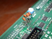
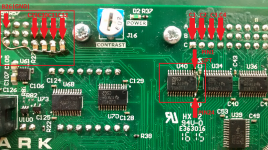
I was thinking k30 to tap the pads yes, but after seeing the post about the leg lift... Yup that one seems like the easiest to do.

I'm not jumping the gun to fix what I've never really seen as a major problem anyways. So of course I'm going to have a look at what DS is cooking up for us before deciding on anything.
 
Could you not just use short kynar (like <1cm) and jumper across from one side of where the chip was to the other (after removing the chip of course)? Rather than over to the CN connector pins. Would look even cleaner.
 
Soldering 8 short wires from the chip inputs to outputs is another option, but you would need to be better at soldering than 99.9% of everyone who knows the blunt end of a soldering iron from the hot end. IMO it's too hard to have 8 wires that close without fucking it up by bridging some wires with solder or moving existing wires as you try to solder the next wire in place. The fan effect and wiring to the connector pins was my solution to that problem.

This is what the PCB looks like at real size. Click 'View Source Image' then click the + sign to see it.
My soldering was done with 8X magnifier and super bright cool white ring light.
Also removing the chip without damaging the PCB requires skill, knowledge and equipment.
I've been doing stuff like this for nearly 20 years. You definitely can't do this just by naked eye with a $10 soldering iron bought at the local hardware store ;)
 

Attachments

  • DSCN8646a.jpg
    DSCN8646a.jpg
    238.5 KB · Views: 273
Leave u40 but lift pin 1 and connect to 3.3V then add the caps and tie them all to ground.
This does seem simple enough. Would it be possible to get a diagram drawn up showing the locations (specifically...the ground, the 3.3v, and the pin1 leg)?

But yes, definitely willing to wait to see what the PCB looks like.
 
Last edited:
PM sent Mr T Guru - definitely would like to send you my kit! cheers
 
The thing is, there probably won't be any tutorial for this. The photo above is clear. Either you can do it or you can't, it's really that simple.
This is why Darksoft wants to fix them properly with the small PCB replacing the chip.

If Darksoft approves I could probably give some info and tips but I won't step on Darksoft's toes. well not much more than I already have anyway :D

We will wait for the 'official' answer :)
You've been really helpful, please provide all the info that you think will help people fix their own kits.
 
I am happy to confirm that I successfully went for the 8 wire fix 8o

Feck knows how it's possible to do it with individual wires...just too damn tiny for my shaky hands! I dug out and old IDE ribbon cable, and it was almost spot on with the spacing. It kept all the wires nicely together. Taped to the board, spaced, then soldered. I'm pretty damn surprised it worked tbh - you'd all laugh/cry if you saw the soldering iron I'm using.

Its a little 'rough round the edges' but my skills are not up to the task of making it look good.

It works, and that's all that matters to me, especially as I've spent the last few months get multiple qsound and normal amps setup in my cabs, to make the most of all boards that have stereo sound.

1AEfSGil.jpg


Thanks to all involved for getting this issue resolved. Love y'all :thumbup:

(FYI It didn't work first time - a wire or two might've been bridged or not connected, and the result was the corrupt graphics below)

VcrE7nZl.jpg
 
If anyone is going to do it themselves, be sure to use single strand wire like Kynar etc.
I haven't looked but maybe the flat cables with single strand wire can be bought somewhere.
IDE cables contain multiple wires and are troublesome if any of those strands go straying, as what likely happened above.
Or at the very least tin the wires and make sure all the strands are together.
 
The IDE cable I used was single strand, and that's the main reason I was able to get it to work.

I can definitely agree to the difficulties in using multi strand - my first attempt was using the inners from a cat6 Ethernet - but it was multi strand, and even pre-coating, it was too wide and generally out of control when I tried to apply.
 
While I am all for swapping caps on my monitors chassis... or even some IC work on older 80's PCBs.... this stuff, I haven't the skill (or equipment) to even attempt.
 
I would've gone for the caps fix too, but (none of) my local maplin only had any in stock.
There's definitely a bit more room to play with, and only one leg to modify on the chip.
 
I would've gone for the caps fix too, but (none of) my local maplin only had any in stock.
There's definitely a bit more room to play with, and only one leg to modify on the chip.
I'll post how to make the Capacitors version later.
 
I'm posting an alternative solution that maybe suitable for more people. I repeat this again. Make sure you know what you're doing as any damage that you make will void any warranty. Do it at your own risk

The second method consists on lifting the leg 1 of U40 and connect this leg to any of the 3.3V points on the PCB like i.e leg 24 of U40. Additionally you need to add 8 Caps of 470 pF or similar to be soldered to the points shown below.

Guru used ceramic caps which are much easier to solder. See attached. Notice that the picture only shows 4 capactiors, the other 4 go on the lower left pins of the connector closer to U40 (same pins as the cable solution with cables of Guru), that means pins C1, C2, C3 and C4.
 

Attachments

  • DSCN8628.JPG
    DSCN8628.JPG
    646.9 KB · Views: 239
  • rework.png
    rework.png
    833.4 KB · Views: 254
^I'm so tempted to try this but a little nervous hahaha.
 
I'm posting an alternative solution that maybe suitable for more people. I repeat this again. Make sure you know what you're doing as any damage that you make will void any warranty. Do it at your own risk

The second method consists on lifting the leg 1 of U40 and connect this leg to any of the 3.3V points on the PCB like i.e leg 24 of U40. Additionally you need to add 8 Caps of 470 pF or similar to be soldered to the points shown below.

Guru used ceramic caps which are much easier to solder. See attached. Notice that the picture only shows 4 capactiors, the other 4 go on the lower left pins of the connector closer to U40 (same pins as the cable solution with cables of Guru), that means pins C1, C2, C3 and C4.
What gauge of wire do you recommend to use to run from leg1 of U40?
 
most important is that cable is single strand. size of pin is 0.5mm, so I guess something slightly smaller like 0.4mm would do the job.
 
The second method consists on lifting the leg 1 of U40 and connect this leg to any of the 3.3V points on the PCB like i.e leg 24 of U40. Additionally you need to add 8 Caps of 470 pF or similar to be soldered to the points shown below.

Guru used ceramic caps which are much easier to solder.
oops. there's a small typo there. voltage going to pin 1 comes from pin 24 of u40 sure, but its 3.3v ;)

I used ceramic caps because that's all I had, plus they were ripped off some junk PCBs which is why they look old.
 
Looks like you did that for at least two other chips as well? Any reason other than initial troubleshooting?
 
Back
Top