What's new

XeD

Grand Master
Joined
Jul 6, 2016
Messages
1,050
Reaction score
912
Location
Vancouver BC Canada
*Edit*
No more salvaging parts from cps3 :) These connector are the same one as conventional pci slot from computer mother boards.

Hello once again

*I do NOT condoned killing a working motherboard for this little diy project. These thing are already hard enough to come by.*

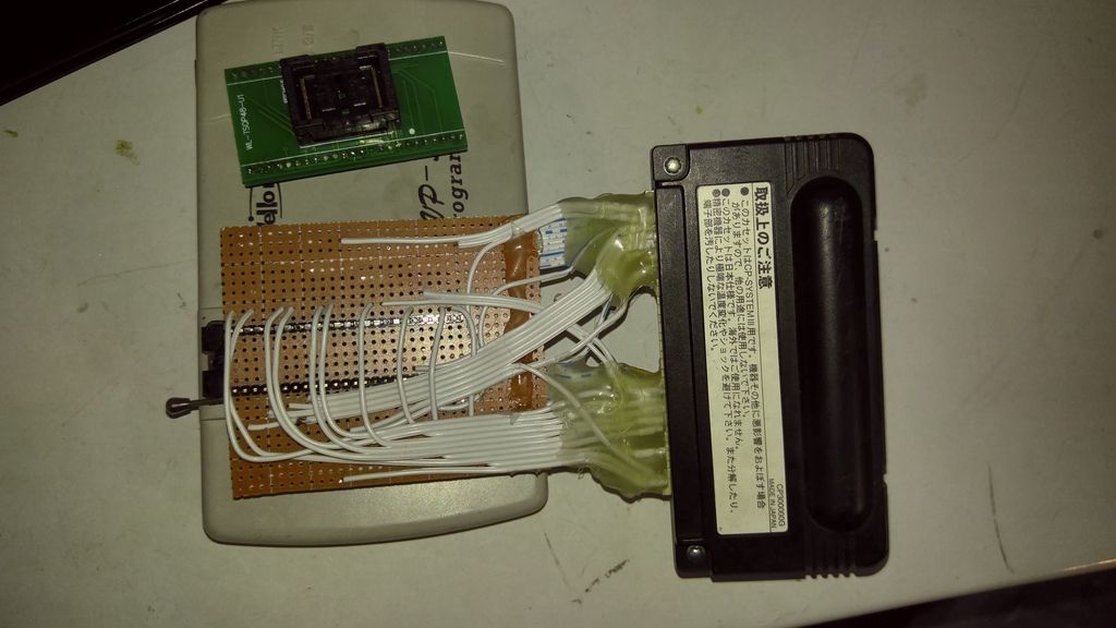
I have a VP390 that I made an adapter for program cps3 carts. I'm having an odd problem, out of my 2 carts 1 will progrom and 1 will not with my diy adapter. Now if I use an actual 29F400 adapter both will program ok. I like to keep using my diy adapter to save on time programming these cart. Does anyone have any idea what I should be looking out for?
 
Last edited:
maybe post some pics and try to be more specific about which ones are programmed and which ones arent.
 
I guess I shouldn't be posting half asleep haha. the adapter on the top work all the time, but I need to desolder the 29f400, yuck. The button monstrosity is my creation. I meter all the pin on the 29f400 to the finger board (except for RB) add pull the edge connector from a parts mobo. This all came about when I was home with my sick kids for a week and half. It seem like a good idea when your sleep deprived and want to save time .

Anyway my creation will work on 1 cart (rev D pcb) but not the other (rev B). In fact when I go to erase the rev B it take along time the 1st time (5min) on the 2nd/3rd it complete it in 5 sec. It will error out right away when I try to program. With the rev D I have reprogram it multiple times and confirm it working in a mobo

P.S. I guess I'm still asleep. Here the pic.
 
Last edited:
No way! You're programming the flash via the cart connector?? That's awesome!

I thought about it a couple of times but thought that it wouldnt' work with all versions of carts, which seems to be your problem if you ask me.

Can you post more pics of your adapter and some rough schematics? I like that!
 
Thanks :D . That's the thing I don't get. Both boards have the same pinout from eeprom to finger board, yet they don't program the same. I was thinking maybe interference/timming issue?
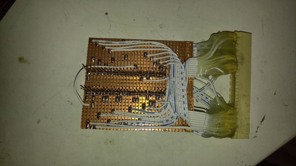
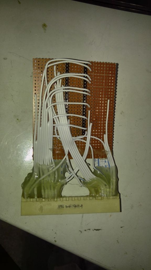
I put the hot glue on because the pins would fall out other wise. The mobo pcb itself has internal jumpers so pulling the socket was my only option. Pin out is as follow. The 29F400 is a 1 to 1 for my programmer. Pin 15 (RP) has no trace to the 29F400.

B48 1. 48 A48
A50 2. 47 B3
B50 3. 46 A8
A51 4. 45 B58
B51 5. 44 B19
A52 6. 43 A14
B52 7. 42 A19
A53 8. 41 B15
N/C 9 40 B20
N/C 10. 39 A15
A1 11. 38 A20
A3 12. 37 A59/60
N/C 13 36 B16
N/C 14 35 B21
N/C 15 34 A16
N/C 16 33 A21
B47 17. 32 B17
B53 18. 31 B22
A55 19. 30 A17
B55 20. 29 A22
A56 21. 28 B1
B56 22. 27 A13
A57 23. 26 A2
B57 24. 25 A58


Last edited:
I got this figure out. It end up being a voltage/current/interference issue? I'll add some picture later. I end up cutting a trace and moving my vcc to the pcb.
 
Very cool idea and implementation. I'm sure if you are programming multiple carts this would be the way to go.
 
so i can flash darksoft bios with this without soldering and desoldering the chip?
 
You still have to open the cart, cut a trace and solder in 1 wire. If you are doing a few its not really worth your time. This was just a fun little proof on concept for me. Having said that I do not condone sacrificing working mobo for this. Mine come from a parts board with a damage custom IC that I have been stealing parts from
 
Thanks :D . That's the thing I don't get. Both boards have the same pinout from eeprom to finger board, yet they don't program the same. I was thinking maybe interference/timming issue?

I put the hot glue on because the pins would fall out other wise. The mobo pcb itself has internal jumpers so pulling the socket was my only option. Pin out is as follow. The 29F400 is a 1 to 1 for my programmer. Pin 15 (RP) has no trace to the 29F400.

B48 1. 48 A48
A50 2. 47 B3
B50 3. 46 A8
A51 4. 45 B58
B51 5. 44 B19
A52 6. 43 A14
B52 7. 42 A19
A53 8. 41 B15
N/C 9 40 B20
N/C 10. 39 A15
A1 11. 38 A20
A3 12. 37 A59/60
N/C 13 36 B16
N/C 14 35 B21
N/C 15 34 A16
N/C 16 33 A21
B47 17. 32 B17
B53 18. 31 B22
A55 19. 30 A17
B55 20. 29 A22
A56 21. 28 B1
B56 22. 27 A13
A57 23. 26 A2
B57 24. 25 A58


very nice. I love the diy set ups and congrats on getting it working right :thumbup:
 
Back
Top