You are using an out of date browser. It may not display this or other websites correctly.
You should upgrade or use an alternative browser.
You should upgrade or use an alternative browser.
- Thread starter brizzo
- Start date
It looks like these are only for the arcade1up cabinets, it will not work with a real arcade PCBI received this PDF from GroovyGameGear about the TurboTwist 2 for arcade1up cabinets
I am no expert but I am curious if this would work for using it with an actual arcade board
Need some experts to way in on this
Why wouldn't the raw output work with a real arcade PCB?It looks like these are only for the arcade1up cabinets, it will not work with a real arcade PCB
That manual leaves a bit to be desired. The J2 PCB at the bottom, how does that interface to the actual spinner.Why wouldn't the raw output work with a real arcade PCB?It looks like these are only for the arcade1up cabinets, it will not work with a real arcade PCB
But it looks like you are right, board is powered with 5V then the raw outputs should be 5V as well

The product description page and that pdf don't really describe exactly how the product works.
The pdf explains the spinner output pulse signalling is UART (not compatible with any original arcade hardware), but also implies it has future support for RAW X1/X2 signaling (this is what arcade games used), but doesn't explain if the pulse rate of these signals is adjustable (probably not, because raw implies it comes directly from the photo sensors)
The pdf explains the spinner output pulse signalling is UART (not compatible with any original arcade hardware), but also implies it has future support for RAW X1/X2 signaling (this is what arcade games used), but doesn't explain if the pulse rate of these signals is adjustable (probably not, because raw implies it comes directly from the photo sensors)
I ordered a Turbo Twist 2 from Groovy Game Gear and I have it running with my original Arkanoid board
Randy was fantastic to deal with.
I used the Dial-A-Rez setting to adjust the spinner (4 and 3/4 revolutions seemed to work great for Arkanoid)
Randy was fantastic to deal with.
I used the Dial-A-Rez setting to adjust the spinner (4 and 3/4 revolutions seemed to work great for Arkanoid)
how did you connect it up? The website pictures and details don’t really show how you’d wire it up. It mentions USB connectors so I always figured it was a mame only spinner. I don’t even see connection headers on the spinner. Mind showing how you wired it up?I ordered a Turbo Twist 2 from Groovy Game Gear and I have it running with my original Arkanoid board
Randy was fantastic to deal with.
I used the Dial-A-Rez setting to adjust the spinner (4 and 3/4 revolutions seemed to work great for Arkanoid)
I ran the left and right wires from my jamma harness into the calibrated inputs (pin 3 and 4)
I ran 5v to pin 1 and GND to pin 2
When I first hooked it up the spinner would move very slowly so I hooked up an arcade button to pin 18 and 19 of the board (Dial-A-Rez)
You press and hold the button down and then turn the spinner about 4 and 3/4 rotations and release the button
That seemed to work good for Arkanoid but you can do the process again until u find what you like
You want the package with the D.A.R.E interface
Hope this helps
Attachments
@MudGuts83 yes they are, just finished assembling another batch last week.
But doesn't the F3 natively support using spinner without my adapter?
But doesn't the F3 natively support using spinner without my adapter?
Stardragon
New User
@brizzo
What an awesome idea and a nice design. And... Puzzle Bobble with Spinners! Okay, I really need one. I hope you still have one left for me.
And a question: Will this work too, if I have my spinners in a cabinet and already wired to left an right or do I have to use the molex connector?
What an awesome idea and a nice design. And... Puzzle Bobble with Spinners! Okay, I really need one. I hope you still have one left for me.
And a question: Will this work too, if I have my spinners in a cabinet and already wired to left an right or do I have to use the molex connector?
Last edited:
@Stardragon I have parts on hand to build another batch; others pm'd me today interested in one as well so I will build more this week. I'll send you a pm.
You must wire the spinners to the 4-pin connectors on the jamma spinner adapter board, otherwise the signals cannot be translated to joystick left/right.
You must wire the spinners to the 4-pin connectors on the jamma spinner adapter board, otherwise the signals cannot be translated to joystick left/right.
Stardragon
New User
Hey guys,
I have recieved a set of Seimitsu spinners, but they do not seem to work with Brizzo's adapter, and I don't have a game to test them.
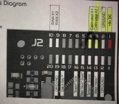
I am trying to figure out what's wrong. Can someone confirm my pinout is correct ?
(this is not a picture of my spinner's board, mine are not broken)

The manual did not include the pinout. It mentions plugging the spinners to a Kaneko Super Nova's CN6 connector, and with the help of Kaneko's manual and the harnesses included with my spinners, I deducted the above pinout.
Is there a simple way to see if a spinner works, without a game ?
I have recieved a set of Seimitsu spinners, but they do not seem to work with Brizzo's adapter, and I don't have a game to test them.
I am trying to figure out what's wrong. Can someone confirm my pinout is correct ?
(this is not a picture of my spinner's board, mine are not broken)
The manual did not include the pinout. It mentions plugging the spinners to a Kaneko Super Nova's CN6 connector, and with the help of Kaneko's manual and the harnesses included with my spinners, I deducted the above pinout.
Is there a simple way to see if a spinner works, without a game ?
Can you post a picture of your complete spinner ?
Testing is easy. Connect ground and power then connect a scope to the 2 remaining pins and look at the pulsetrains. They should be offset.
Thanks for the help.
My spinners are the same ones as on this picture. I've seen members with the same ones on this thread. I'll post an actual picture of mine if need be.
Those are LS-29 with the old PCB. Look here:
https://wiki.arcadeotaku.com/w/Spinner#Seimitsu_LS-29_Pinout
If you do not have a scope, do you have a simple logic analyser like the Salea Logic? If you do not have any of these tools it will be hard to diagnose your spinner.
https://wiki.arcadeotaku.com/w/Spinner#Seimitsu_LS-29_Pinout
If you do not have a scope, do you have a simple logic analyser like the Salea Logic? If you do not have any of these tools it will be hard to diagnose your spinner.
Those are LS-29 with the old PCB. Look here:
https://wiki.arcadeotaku.com/w/Spinner#Seimitsu_LS-29_Pinout
If you do not have a scope, do you have a simple logic analyser like the Salea Logic? If you do not have any of these tools it will be hard to diagnose your spinner.
Unfortunately I do not have any of these tools...
The AO wiki page states:
Seimitsu LS-29 Pinout
Pin1: X1, Pin2: +5 Volts, Pin3: GND, Pin4: X2So it seems I would have got my wiring wrong. It seems very unlikely, as I checked multiple times with my harnesses, but I'll try inverting those wires, hoping nothing got damaged out of this.
I'll post pictures of my harnesses.
