You are using an out of date browser. It may not display this or other websites correctly.
You should upgrade or use an alternative browser.
You should upgrade or use an alternative browser.
- Thread starter iCEQB
- Start date
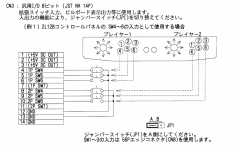
Again, if the link you posted to the notes on Arcade Otaku are to be believed then:Thanks! Do you happen to know the pinout for the CN3 expansion connector for the Rev B?
Code:
 1 - 5VDC Out
 2 - 5VDC Out
 3 - 5VDC Out
 4 - P1 button 4
 5 - P1 button 5
 6 - P1 button 6
 7 - p1 button 7
 8 - p2 button 4
 9 - p2 button 5
10 - p2 button 6
11 - p2 button 7
12 - GND
13 - GND
14 - GND
Last edited:
also here https://wiki.arcadeotaku.com/w/JVS#Sega_838-13683-93
I'm 99% sure "rev A" and "rev b" has identical pinout
I'm 99% sure "rev A" and "rev b" has identical pinout
I feel like there is conflicting information regarding the Rev A & B.also here https://wiki.arcadeotaku.com/w/JVS#Sega_838-13683-93
I'm 99% sure "rev A" and "rev b" has identical pinout
Some websites say the pinout is the same, while others say the pinout is different.
if you already had that, why did you need to ask me about it?See pic from Sega Manual
I found it after I asked you, here:if you already had that, why did you need to ask me about it?See pic from Sega Manual
http://www.neo-geo.com/forums/showt...838-13683-93&p=3641669&viewfull=1#post3641669
Last edited:
ArcSys101
Grand Master
I have a lot of
Jvs type 1 , three of them
Jvs type 1.5 and one of them
Jvs type 3 ,two of them with the wires from ttx2
Planning to let them go
This info has been very helpful and I thank this forum
Jvs type 1 , three of them
Jvs type 1.5 and one of them
Jvs type 3 ,two of them with the wires from ttx2
Planning to let them go
This info has been very helpful and I thank this forum
@twistedsymphony I need your help.
I'm using the Rev B Sega JVS to Jamma adapter. I had a cable made that goes from CN8 on the Blast I/O to the 14pin input on the JVS/Jamma adapter. It is wired exactly as you posted, but I am not getting any input on buttons 4-6 in the Naomi I/O test menu.
1 - 5VDC Out
2 - 5VDC Out
3 - 5VDC Out
4 - P1 button 4
5 - P1 button 5
6 - P1 button 6
7 - p1 button 7
8 - p2 button 4
9 - p2 button 5
10 - p2 button 6
11 - p2 button 7
12 - GND
13 - GND
14 - GND
Last edited:
what pinout did you use for CN8?
and what position is your jumper in?
and have you confirmed continuity between the buttons in your control panel and the CN8 connector to make sure your cab's internal wiring is correct?
and what position is your jumper in?
and have you confirmed continuity between the buttons in your control panel and the CN8 connector to make sure your cab's internal wiring is correct?
Last edited:
Try the pinout on the ao wiki..@twistedsymphony I need your help.
I'm using the Rev B Sega JVS to Jamma adapter. I had a cable made that goes from CN8 on the Blast I/O to the 14pin input on the JVS/Jamma adapter. It is wired exactly as you posted, but I am not getting any input on buttons 4-6 in the Naomi I/O test menu.
1 P1 light kickwhat pinout did you use for CN8?
and what position is your jumper in?
and have you confirmed continuity between the buttons in your control panel and the CN8 connector to make sure your cab's internal wiring is correct?
2 P2 light kick
3 P1 medium kick
4 P2 medium kick
5 P1 strong kick
6 P2 strong kick
7 GND
8 GND
Jumper is on A
Not yet but my Capcom I/O works with cn8 going to a cps2 kick harness for buttons 4-6
well if your CPS2 kick harness works then that confirms your cab wiring is good.
Just to confirm you're tying the ground pins on the JVS IO connector to both of the ground pins on CN8?
Just to confirm you're tying the ground pins on the JVS IO connector to both of the ground pins on CN8?
Pins 7 & 8 on CN8 go to pins 13 & 14 on the JVS IO connector.well if your CPS2 kick harness works then that confirms your cab wiring is good.
Just to confirm you're tying the ground pins on the JVS IO connector to both of the ground pins on CN8?
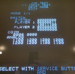
And in the NAOMI System test mode (NOT game test mode) you don't see ANY of the button bits changing?
I think I figured out the problem. It looks like buttons 4,5,6 on the control panel, register as buttons 6,7,8 on the I/O.And in the NAOMI System test mode (NOT game test mode) you don't see ANY of the button bits changing?
Attachments
Last edited:
so it looks like your IO is using the Rev A pinout
Were you able to get buttons 4,5,6 to work on a Rev B IO?so it looks like your IO is using the Rev A pinout
Last edited:
@invzim
Arcade Otaku wiki:
Sega 838-13683-02 = Rev A
Sega 838-13683-93 = Rev B
"The operation and pin-out of extra buttons is identical"
1 - 5VDC Out
2 - 5VDC Out
3 - 5VDC Out
4 - P1 button 6
5 - P1 button 7
6 - P1 button 8
7 - p1 button 9
8 - p2 button 6
9 - p2 button 7
10 - p2 button 8
11 - p2 button 9
12 - GND
13 - GND
14 - GND
Last edited:
shouldn't the JAMMA Loom on a Blast have buttons 4 and 5 populated already?
