Not unless you use the Sega 2L12B adapter, which reroutes buttons 4 and 5 to the Jamma edge.shouldn't the JAMMA Loom on a Blast have buttons 4 and 5 populated already?
https://wiki.arcadeotaku.com/w/Sega_2L12B_Adapter
Not unless you use the Sega 2L12B adapter, which reroutes buttons 4 and 5 to the Jamma edge.shouldn't the JAMMA Loom on a Blast have buttons 4 and 5 populated already?
Yes, it has them. They're routed to the regular 1P and 2P connectors.shouldn't the JAMMA Loom on a Blast have buttons 4 and 5 populated already?
I have no idea what the heck that thing is. I don't even understand why you would need one?Not unless you use the Sega 2L12B adapter, which reroutes buttons 4 and 5 to the Jamma edge.
wiki.arcadeotaku.com/w/Sega_2L12B_Adapter
I feel like this information is either wrong, or your IO board is using older revision code.Click here
Under CN6:
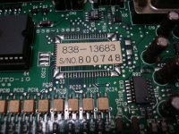
Note7:The SEGA I/O board JVS to JAMMA (838-13683-91 Rev.A) can be configured as BILLBOARD INPUT or Control SW6~8 OUTPUT.
Note8:With SEGA I/O board JVS to JAMMA (838-13683-93 Rev.B),MCU redefined the Control SW4~7 OUTPUT.
Differences between Rev A & B
It sends the wires that usually go to the extra buttons 10pin connector (CNI have no idea what the heck that thing is. I don't even understand why you would need one?Not unless you use the Sega 2L12B adapter, which reroutes buttons 4 and 5 to the Jamma edge.
wiki.arcadeotaku.com/w/Sega_2L12B_Adapter
That page is junk. I want to delete the whole thing from the wiki.
") to the Jamma edge using the wiring for P1 & P2.
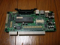
to the Jamma edge using the wiring for P1 & P2.Let me check this...If you got into NAOMI System Test Screen and do the JVS Test what is the ID of the board? it should be something like "SEGA ENTERPRISES,LTD.;I/O 838-13683B ;Ver1.07;99/06"Click here
Under CN6:
Note7:The SEGA I/O board JVS to JAMMA (838-13683-91 Rev.A) can be configured as BILLBOARD INPUT or Control SW6~8 OUTPUT.
Note8:With SEGA I/O board JVS to JAMMA (838-13683-93 Rev.B),MCU redefined the Control SW4~7 OUTPUT.
Differences between Rev A & B
Wrong.It sends the wires that usually go to the extra buttons 10pin connector (CN
Definitely! It is possible to update the firmware on the JVS adapter?First think it it's worth seeing if the newer Firmware for that JVS IO mapps 4 and 5 to the extension header. If not I wonder if the firmware could be patched to do that.
I don't understand what's the problem then. You want to use the auxiliary 10-pin AMP UP connector for your kick buttons? There's a very easy solution to this. You snip the 4th and 5th button wiring that goes from the jamma edge connector to CN5 and reroute it to CN8. You need a 8-pin JVS NH connector and some female pins. Remember to splice ground to the last pin. If you wanted you could do this on the underside of the IO board too. If you add diodes you don't even have to make any cuts, just add jumper wires.@nem not wrong sorry.
I am very familiar with how the wiring works for P1, P2 & Extra buttons, but I appreciate you taking the time to explain it.
Agreed. It's a-shame because some people claimed that the Sega I/O felt more responsive than the Capcom I/O.so it seems that AO wiki information about the newer firmware having different button mapping is wrong.
Talki to @Mitsurugi-w. He may be able to help.Is there a ready made harness available for the CN3 header on the Sega JVS IO rev B? Would prefer not to crimp one myself as I'm lacking the tools at the moment to get that done but if nothing is out there, what is the correct 14 pin connector to use here?