You are using an out of date browser. It may not display this or other websites correctly.
You should upgrade or use an alternative browser.
You should upgrade or use an alternative browser.
- Thread starter ShootTheCore
- Start date
I think you can align it ...
Machine translation:
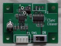
About VR1 Although the variable resistor VR1 on the board has been adjusted so that it can
be normally displayed with the combination of the TAITO F3 system board
and FRAMEMEISTER (frame meister) XRGB-mini, by adjusting this
resistance value, There may be. If you do not see it correctly please adjust this VR1 with a precision screwdriver etc.
So looks like that tiny variable resistor can take care of the problem. My next question is where exactly do you inject this device in the chain of devices? Let's assume you are using an F3 with a HAS supergun going to a Scart switcher to a PVM.
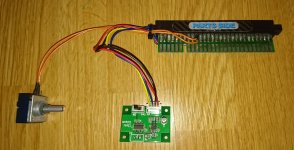
Well I made a JAMMA adapter board, let me see if I can snap a picture.So looks like that tiny variable resistor can take care of the problem. My next question is where exactly do you inject this device in the chain of devices? Let's assume you are using an F3 with a HAS supergun going to a Scart switcher to a PVM.

edit: ignore the volume control

Last edited:
Well, I emailed them to place an order. Lets see what happens.Well I made a JAMMA adapter board, let me see if I can snap a picture.So looks like that tiny variable resistor can take care of the problem. My next question is where exactly do you inject this device in the chain of devices? Let's assume you are using an F3 with a HAS supergun going to a Scart switcher to a PVM.
edit: ignore the volume control
Since it works for RTW, then maybe someone can recreate what this circuit does in a new board that can be installed on the F3 motherboard. Doesnt seem like it would cost much to have this made. I requested 2 of these, if it goes through I can donate one to have someone reproduce it/figure out how it works and maybe a better fitment solution can be made for the F3.
The cable would need to be custom made (really easy), either Scart to VGA, or 8pin mini DIN to VGA. I'll see if I have parts to build one, and if I do, I could send you such cable for testing.But I don't know what cable I'd use to go from the HAS's DIN output to VGA. @RGB what are your thoughts on outputting HAS to VGA?
That's pretty much what's used in the HAS V3.0 - the EL1883 with a potentiometer to change the internal timing (it affects the H/V Sync which are later combined to form the Csync again).Since it works for RTW, then maybe someone can recreate what this circuit does in a new board that can be installed on the F3 motherboard. Doesnt seem like it would cost much to have this made. I requested 2 of these, if it goes through I can donate one to have someone reproduce it/figure out how it works and maybe a better fitment solution can be made for the F3.
@rtw does the Taito F3 +HAS V3.0 and/or V3.1 + OSSC combo work for you? Perhaps it's some OSSC setting?
It does fix the horizontal position, but remember that the potentiometer affects the VSync, too, so at some point when you adjust the horizontal position, the picture will move up/down by one or more lines as well. The vertical movement is negligible, but if you overdo it, the image will slightly shake (it's even visible on the CRT) or lose sync completely. The ideal solution would be a circuit that allows to control the HSync only.let us know how it goes. I'd be inclined to add this if it fixes the horizontal alignment issue so I don't have to re-adjust everytime I swap out the F3.
Last edited:
ShootTheCore
Legendary
That would be wonderful - if you have the parts, just PM me with a total cost for the parts, shipping to the US and your time. I appreciate it.The cable would need to be custom made (really easy), either Scart to VGA, or 8pin mini DIN to VGA. I'll see if I have parts to build one, and if I do, I could send you such cable for testing.But I don't know what cable I'd use to go from the HAS's DIN output to VGA. @RGB what are your thoughts on outputting HAS to VGA?
I have the taito scaler so the F3 works perfectly in my cabs. I have not tried it with the HAS v3.1 + OSSC yet.That's pretty much what's used in the HAS V3.0 - the EL1883 with a potentiometer to change the internal timing (it affects the H/V Sync which are later combined to form the Csync again).
@rtw does the Taito F3 +HAS V3.0 and/or V3.1 + OSSC combo work for you? Perhaps it's some OSSC setting?
@jassin000 I think you have the latest HAS, can you test the F3 with it and your OSSC + OLED.
J
jassin000
Tested, didn't work.
Unlike some of the picky sync PCBs I've got (where enabling the HAS's sync regen circuit is enough) nothing I've yet tried makes the OSSC accept F3 (it will however work with xRGB mini with HAS's regen on).
Unlike some of the picky sync PCBs I've got (where enabling the HAS's sync regen circuit is enough) nothing I've yet tried makes the OSSC accept F3 (it will however work with xRGB mini with HAS's regen on).
@ShootTheCore, can you post a pic of the issue you are experiencing? Like what @jugu says, I have issues with alignment. Wonder if once you guys come up with this solution, it fixes the alignment/geometry stuff. The CPS3 does this thing with alignment too. Wondering if what is fabbed here fixes that as well.
Thanks for the pic. The machine translated manual was a bit hard to understand - if you switch the device off, can you toggle between let's say an adjusted F3 signal and the "default" unadjusted sync signal?Well I made a JAMMA adapter board, let me see if I can snap a picture.So looks like that tiny variable resistor can take care of the problem. My next question is where exactly do you inject this device in the chain of devices? Let's assume you are using an F3 with a HAS supergun going to a Scart switcher to a PVM.
edit: ignore the volume control
Did you just use their "Contact Us" page to order? I assume you used English?Ok, so my order seems to have gone through, waiting on confirmation.
It's the EL1883 that is used to extract the H and V sync, and then the 74F86 or 74HC86 to combine them. Combining the signals using the XNOR works for most devices, but it's not ideal and it could be that the OSSC is more picky about it. I'm wondering if we could get better results by feeding the OSSC separate H and V sync signals via the VGA connector.
J
jassin000
This!I'm wondering if we could get better results by feeding the OSSC separate H and V sync signals via the VGA connector.
Trust me I've tried all sorts of sync regens with F3, it just won't work with OSSC's (xRGB mini Framemeister is AOK) SCART input.
So what WOULD happen if separated H and V was sent to the VGA connector?
Also, to bump this point:
This was the suggestion from Chris over at martin-jones.com (<- Interesting read on arcade Sync issues).
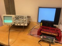
Could someone with a dual-trace oscilloscope could take a look at the sync pulses on one channel and the video output on another (R, G or B, it doesn't matter which)?I agree. I have enough know-how to map out the sync signals with an oscilloscope, but I don't have the electrical engineering knowledge on what to do with building a correction circuit afterward. If I mapped out the signals and posted them on here, would that be of any use to someone that does have the necessary know-how?really the best would be to map out the F3's sync signal with a scope and compare it to a system that runs the same resolution but without sync problems. Then once you've clearly identified the problem can you work on a solution.
This was the suggestion from Chris over at martin-jones.com (<- Interesting read on arcade Sync issues).
skate323k137
Enlightened
I'd be happy to if I had a scope  one of these days I'll find one.
For what it's worth every jamma signal is different, the F3 just seems to sit a little to the side compared with most other boards. The difference is almost an inch to the side on a 27 inch CRT. Not a big deal in a cab but a pain for scalers.
 one of these days I'll find one.
For what it's worth every jamma signal is different, the F3 just seems to sit a little to the side compared with most other boards. The difference is almost an inch to the side on a 27 inch CRT. Not a big deal in a cab but a pain for scalers.


