What's new
I'll pass on the glue gun.
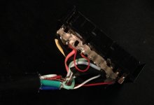
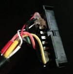
Would a multimeter help me figure out which wire is properly connected to the gold point or not? I won't be able to do much about until next weekend when I should have my hands on a good paste flux.
Good choice. ;)

Yes a multimeter can be used to confirm your wires are properly connected. You would put the multimeter in continuity mode, then use one probe to touch the pad on your CPS2 multi (not touching your wire) and the other probe touching the pin on the CPS2 B board (again not touching your wire).
 
Your CPS2 multi isn't ready until it looks like this... ;)

drakon.png


<X <X <X
Holy hot glue and zip ties!
put the multimeter in continuity mode, then use one probe to touch the pad on your CPS2 multi (not touching your wire) and the other probe touching the pin on the CPS2 B board
That ^

Anytime I'm questioning a solder joint I check continuity.
Sometimes a wire can look ugly but be physically connected just fine, it's worth checking before blindly resoldering everything.
 
Apparently its ok to use snot for insulation on a £24 cable from ret********cables.co.uk too...
 

Attachments

  • IMG_4334.JPG
    IMG_4334.JPG
    453.7 KB · Views: 251
  • IMG_4337.JPG
    IMG_4337.JPG
    681.9 KB · Views: 225
Hello,

I wanted to do the update and the soldering but I'm a bit confused because:

Everyone doing the mod says he first updated the firmware and then did the wiring...
However the warning in the first post says the complete opposite?!

What is the right order of doung this now?

Thanks for lettig me know!
 
WARNING!!!! DO NOT INSTALL THE WIRES UNTIL AFTER UPDATING THE FW!!!! IF THE WIRES ARE INSTALLED WHILE TRYING TO UPDATE THE FW YOU WILL CORRUPT THE BOOT-LOADER ON THE KIT AND YOU WILL HAVE TO REWRITE IT USING A DISCOVERY!!!
Hello,

I wanted to do the update and the soldering but I'm a bit confused because:

Everyone doing the mod says he first updated the firmware and then did the wiring...
However the warning in the first post says the complete opposite?!

What is the right order of doung this now?

Thanks for lettig me know!
That warning? It says to do the FW update first and then connect the wires AFTER. That is the correct procedure.
 
OMG.... I'm feeling pretty stupid right now...

Read it like 20 times but since it was late at night me and a friend understood it the wrong way for some reason...

Thanks a lot and sorry to for the inconvenience...

At another forum I probably would get kicked out by now... ;)
 
OMG.... I'm feeling pretty stupid right now...

Read it like 20 times but since it was late at night me and a friend understood it the wrong way for some reason...

Thanks a lot and sorry to for the inconvenience...

At another forum I probably would get kicked out by now... ;)
I know some forums that might....
But not here buddy, no worries ;)
 
I have a rev. 7 board myself so I don't expect issues while updating when I get to it, but a buddy of mine has a rev 3 or 4 board.
Haven't opened it up yet, but should I add a 4K7 resistor to A32/C32 if the board doesn't have one?
 
How I would approach it:

If it ain't broke, don't fix it: Update the firmware and connect up the wires, if it works, great! If not, add the resistor to see if it helps.

It really seems to be completely random which rev 3 and 4 boards require it, others here have had no issues but in at least 1 case it just wouldn't work no matter what.

I couldn't get a rev 3 board that crossed my path to load keys until I removed all the EPROMs, and then it worked perfectly. If this board was to run the multi I'd say it would need the resistor
 
Seeing all those professional mods I started collecting the stuff I'll need to install the Kit.
But I am at a loss as to what plug is used for where the key writing wires are attached.

Does anybody here have some part number or at least info what it is? It kinda looks like a Hirose crimp plug but...
I posted this back on page 2:

JST NH series
Housing: H6P-SHF-AA
Pins: SHF-001T-0.8BS
uses 22-28 AWG wire

You can order directly through JST:
https://order.jst-mfg.com/InternetS...tedPage=mainContent&countryId=840&language=en
There is also a wiring diagram on the first post of this thread:

https://www.arcade-projects.com/forums/index.php?attachments/6391/
 
Updated my CPS2 multi with the key writing firmware today and it works great! Had a little scare after attaching the 4 wires since all I got was a light green screen, but I think my B board wasn't sitting properly. Re-seated the board and everything was working after. Phew. Also, in case anyone is wondering, dupont jumper cables can also work to connect to the CN9 connector - that is what I did since I'm cheap and didn't want to wait for a special connector to arrive.
 
Also, in case anyone is wondering, dupont jumper cables can also work to connect to the CN9 connector - that is what I did since I'm cheap and didn't want to wait for a special connector to arrive.
I went that route also.
 
i think i will try the update.is there a proper install video of the wires and where and which file to use for the firm update.

no battery or the flash

thanks
 
Page #1, post #1 should have all the info ;)

The flash.zip file is the one you need + the latest rom pack from Smokemonster
 
Ok. What ist the other one good for. The battery zip.
Copy/paste from post #1

For the suicided versions like from Team Avalaunch just place a 20bytes file full of FFFFFFF in the game directory. See attached file Nobattery. Now you can use the kit even to restore dead CPS2 B Boards!!!
 
Back
Top