What's new
with both CF and GD-ROM the serial cable is crazy finicky... they don't like long cables, they don't like dirty connectors, some non-sega cables don't like to work well, and the wires in them are really thin so they break often. Net-Booting is going to be more reliable for this reason since it removes that shitty cable completely from the equation.

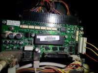
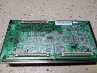
Similarly the connection between the NAOMI main board and the cart (or DIMM board) is temperamental as well. I was having errors regularly on a few cart and one of my DIMM boards... cleared them all up with cleaning the pins and fixing a few slightly bent pins on one of the carts.

sourcing properly sized screws to keep pressure on the connection after cleaning /fixing any pins will do wonders to improving reliability too.
 
sourcing properly sized screws to keep pressure on the connection after cleaning /fixing any pins will do wonders to improving reliability too.
Yup this... After I received my Jorge multi cart I screwed all for sides down as hard as I could without over tightening.
That MF'n cart is never coming off that motherboard! :evil:
 
Hey @xanderXone,

Sent you the connector today. You should have it Monday, Tuesday at the latest. The connector I sent you covers all but the last pin on the I/O connector. The last pin is just ground, so don't worry if it is exposed. It will still work fine. Just make sure when you connect it to your I/O board, you align socket 1 on the connector to pin 1 on the I/O board and you'll be fine. Socket one on the connector will be the left most socket when you are holding the connector with the wires pointing towards you and the security latch clip facing up. When connecting to the I/O board, the security latch clip will face towards the middle of the I/O board instead of out to the edge of the I/O board.

I added in the 3rd grounding wire. From what was said earlier in this post, you most likely can use the ground that is already grounding your other buttons. If so, you can just clip off that grounding wire. Check first before you do and keep us posted on your progress.
 
10-4. Thanks again @acblunden2

I'll post some more pics once I get the new buttons and sticks installed and let you guys know if I run into any problems.
 
The wood underlayer of my control panel appeared to be broken previously and glued back together. Not ideal, but it seemed to be fine... Up until I knocked it over and it closed to hard and shattered...smh
IMG_20171209_004425.jpg

Ended up making a new one out of some plywood I had lying around. I'm kind of glad that it broke now since the new one is much stronger.

IMG_20171209_004522.jpg
 
Looks like a router's work! Good ole' router. The most versatile power tool in a woodshop!
 
Looks like a router's work!
I actually used only a jigsaw and a holesaw to construct the new piece!

The router I own is a trim router, and from what I read not ideal for this application. A plunge type router would have been the way to go, but I didn't want to have to buy one so I went with the jigsaw instead.

After a good filing and sanding I'm happy with the results.
 
I installed the kick harness and wired everything up, but button six for both players is not working for some reason.

My first thought was that grounding them to the other buttons that are on the jamma edge was the likely problem, but once I grounded them to the new kick harness instead they are still not functioning.

Does anyone have any ideas on how to fix this?

Many thanks in advance!
 
Do I need to move jumper JP1?

Will I still be able to use my GD-Rom if I move this?
 
There is a jumper on your I/O board that you have to set too. See if you can move that to the other position to see if that works and report back.
 
I don't see any jumper on the I/O ∆∆∆∆
 

Attachments

  • IMG_20171212_200818.jpg
    IMG_20171212_200818.jpg
    515.3 KB · Views: 60
I'm stumped...

I believe the pin outs are correct for the new harness, so I don't think that is the issue.

Player 1 button six is in slot 4 of the harness and Player 2 button six in slot 8 which appears to be correct per the schematic.

https://wiki.arcadeotaku.com/w/JVS

The link mentions a jumper "JP1" but this is nowhere to be found on my I/O board 838-13683-02...
 
Since your I/O board is version Sega 838-13683-02, looks like you do have it wired correctly. My mistake. So looks like you just need to move the jumper to position A. Looks to be in position B at the moment.

I have it encircled in RED.
IMG_20171212_200818.jpg
 
Last edited:
Thank you for pointing out the jumper location @acblunden2, and for all of your help.

After moving the jumper all six buttons for both players are working great!

There isn't much info for my I/O online besides saying it is virtually identical to the 838-13683-93, but jumper JP-1 is in a totally different location. None of my searches definitively showed it's location, and I am too much of a noob to see it even when it is right in front of my face, so I apologize for my ignorance.
 
We all start somewhere,ironically enough.

You did a good job. Especially considering that I incorrectly wired the harness for version B of the Sega I/O. You were able to figure that out and rewired it on your own perfectly. This thread should help others. Someone PM'ed me about this same thing with the Sega I/O. I told them to ask in this thread. They never did. I am sure that person is lurking and seeing this.
 
I was getting a lot of error 21's for some reason so I decided to take off the dimm board and check it out. It looks like there is some white residue on it.

Would I be able to clean this off? If so what is the best method of doing this?
 

Attachments

  • IMG_20171214_145251.jpg
    IMG_20171214_145251.jpg
    587.9 KB · Views: 47
As I said above, even with a totally clean connectors I would still get error 21 daily with my DIMM+CF Kit.
This is a major reason why I didn't recommending sticking with this hardware, IMO it's unreliable at best.
 
That residue is very common on the DIMMs.

Error 21 can be caused by a few things:


Incorrect Bios (version is usually too old)

Incorrectly loaded game file (Bad CF card or game loaded to card wrong)

Bad game file (Not using a game file designed for CF loading or netbooting)

Trying to load a non-naomi game (yes I've seen this issue)
 
I'm using a GD-Rom, which was working yesterday but for some reason is not working today.

I'm doing a dim board test through the test menu and am getting a message saying "ERROR:DIMM BOARD TIMEOUT"

When I exit the test menu now I'm getting "ERROR 22"
 
Back
Top