You are using an out of date browser. It may not display this or other websites correctly.
You should upgrade or use an alternative browser.
You should upgrade or use an alternative browser.
- Thread starter ekorz
- Start date
samplehunters
Student
Are you sure? from https://cdn.discordapp.com/attachments/401250804062748683/421818275261972480/L4D_Schematic.zipYes, but it's ok
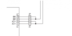
I have looked into the vewlix schematics and it's :
1 - 12v
2 - 12v
3 - GND
4 - GND
My fast I/O come to vewlix cabinet.

Arf!
I have looked into this schematics : https://wiki.arcadeotaku.com/images/5/5a/Taito_Vewlix_L_Manual_Part_3.pdf
On page 33.
My bad
I have looked into this schematics : https://wiki.arcadeotaku.com/images/5/5a/Taito_Vewlix_L_Manual_Part_3.pdf
On page 33.
My bad
Attachments
samplehunters
Student
Friend, all the info is on the 1st page of this thread. Have a look at this picture. 

I have 12v connected on pin 1 and 5v connected on pin 2.
ground on pin 3 and 4
initially I put 12v on pin 2 as well which burnt my IO...
My guess is the dual 12v is for the original Vewlix IO and not the ‘universal’ IO board
ground on pin 3 and 4
initially I put 12v on pin 2 as well which burnt my IO...
My guess is the dual 12v is for the original Vewlix IO and not the ‘universal’ IO board
Correct, I also mention that in the 3rd post of this threadFriend, all the info is on the 1st page of this thread. Have a look at this picture.
")
Yes the L4D schematics are correct for fastio boards that are pulled from cabinets. I wouldn't trust Vewlix anything because of how modular they are unless you've matched your pcb model to the specific one in that manual.
thanks PascalP. with your help i was able to find this info from another post on the forum.
Housing: XLP-04V
order.jst-mfg.com/InternetShop…6831500#showProductDetail
Contacts: SXF-01T-P0.7
order.jst-mfg.com/InternetShop…earch=top#showProductList
thanks i was able to get these parts locally.
Housing: XLP-04V
order.jst-mfg.com/InternetShop…6831500#showProductDetail
Contacts: SXF-01T-P0.7
order.jst-mfg.com/InternetShop…earch=top#showProductList
thanks i was able to get these parts locally.
Last edited:
@PascalP I have the K91X1243A fast I/O that i bought to replace my stock vewlix L AMI jvs pcb assy. From the stock vewlix harness P1 connector that went into P1 on my jvs pcb i multi meter 12v 12v G G.I have 12v connected on pin 1 and 5v connected on pin 2.
ground on pin 3 and 4
initially I put 12v on pin 2 as well which burnt my IO...
My guess is the dual 12v is for the original Vewlix IO and not the ‘universal’ IO board
The fast I/O has a 4 pin xl-jst. I'm understanding that you and @sammargh are saying this universal fast I/O needs pin1 12v, pin2 5v, pin3 G, pin 4 G? So i'm ordering the xl-jst and crimp connectors to build a plug, is it ok to use one existing 12v and both grounds from my existing harness P1 and i'll hijack a 5v from somewhere else for pin2? Am i correct assuming the 4pin xl-jst on the the universal fast I/O are inputs? I haven't received my Nesica rfid reader yet, but does the reader plug into the universal fast I/O also for power or will the RFID need separate power?
Hackcell
Grand Master
Are buttons 5 and 6 working on your K91X1243A board?@PascalP I have the K91X1243A fast I/O that i bought to replace my stock vewlix L AMI jvs pcb assy. From the stock vewlix harness P1 connector that went into P1 on my jvs pcb i multi meter 12v 12v G G.
The fast I/O has a 4 pin xl-jst. I'm understanding that you and @sammargh are saying this universal fast I/O needs pin1 12v, pin2 5v, pin3 G, pin 4 G? So i'm ordering the xl-jst and crimp connectors to build a plug, is it ok to use one existing 12v and both grounds from my existing harness P1 and i'll hijack a 5v from somewhere else for pin2? Am i correct assuming the 4pin xl-jst on the the universal fast I/O are inputs? I haven't received my Nesica rfid reader yet, but does the reader plug into the universal fast I/O also for power or will the RFID need separate power?
For me they are, have to dig back through the thread to find the exact model numberAre buttons 5 and 6 working on your K91X1243A board?
thank you . I will try to get my use io working for my x4.
Red cable connects the USB IO to the main x4 unit. Love life after school requires each USB device to be connected to a specific USB port on the back on the x4 main unit. Here's a picture from the manual. I'm not sure if this is the case for any other games as I don't own any other x4 games. Use Google translate to work out which usb item is the IO.

Does this one could work with X4 ?TAITO also make a JAMMA version called the FAST IO AMP P.C.B.
It also has a large connector for the extra buttons.
The socket on the PCB is labeled: DDK 5S53 T 0
Anyone have any idea what kind of connector I should use ?

