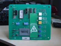
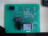
So the work continues on the Sega Rally 3....
I have two connectors hanging out the side that should go to the coin tower.
1) 4-pin - Bottom left on diagram.
2) 9-pin - Top left on diagram.
And I've found a spare VTS-STW PCB in the bits box, which is a single cab unit - no cables though.....


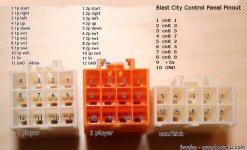
And on AO a pinout...
VTS 18-pin
1
2
3 Vol C - VCC
4 Vol C - VOL
5 Vol C - GND
6 Demag
7 Demag
8 Test
9 Service
10 GND
11
12
13 VOL B - VCC
14 VOL B - VOL
15 VOL B - GND
16 VOL A - VCC
17 VOL A - VOL
18 VOL A - GND
VTS 15-pin
1
2
3
4 VOL A - GND
5
6
7
8
9 VOL A - VCC
10 TEST
11
12
13
14 VOL A - VOL
15 Service
VTS 9-pin
1 GND
2 VOL B - VOL
3 VOL C - VOL
4 VOL B - GND
5 VOL C - GND
6 GND
7 VOL B - VCC
8 VOL C - VCC
9 +12V
How do I wire the damn thing up and what order are the pins laid out on the connectors?

Can I assume the pins are in the same order as this lifted from AO. ie looking into the female socket on the back of the pcb pin 1 is the top right corner where top is designated be the catch?

I have two connectors hanging out the side that should go to the coin tower.
1) 4-pin - Bottom left on diagram.
2) 9-pin - Top left on diagram.
And I've found a spare VTS-STW PCB in the bits box, which is a single cab unit - no cables though.....


And on AO a pinout...
VTS 18-pin
1
2
3 Vol C - VCC
4 Vol C - VOL
5 Vol C - GND
6 Demag
7 Demag
8 Test
9 Service
10 GND
11
12
13 VOL B - VCC
14 VOL B - VOL
15 VOL B - GND
16 VOL A - VCC
17 VOL A - VOL
18 VOL A - GND
VTS 15-pin
1
2
3
4 VOL A - GND
5
6
7
8
9 VOL A - VCC
10 TEST
11
12
13
14 VOL A - VOL
15 Service
VTS 9-pin
1 GND
2 VOL B - VOL
3 VOL C - VOL
4 VOL B - GND
5 VOL C - GND
6 GND
7 VOL B - VCC
8 VOL C - VCC
9 +12V
How do I wire the damn thing up and what order are the pins laid out on the connectors?
Can I assume the pins are in the same order as this lifted from AO. ie looking into the female socket on the back of the pcb pin 1 is the top right corner where top is designated be the catch?

Last edited:

