You are using an out of date browser. It may not display this or other websites correctly.
You should upgrade or use an alternative browser.
You should upgrade or use an alternative browser.
- Thread starter Derick2k
- Start date
they also make thermal adhesive for heat syncs. I use it on my 3D printer with some generic heat syncs to keep the stepper motors cool.
https://www.amazon.com/Arctic-Alumi...8&qid=1515597765&sr=8-6&keywords=thermal+glue
it's strong enough that they'll never fall off but weak enough that you can break them off if you need to remove them.
https://www.amazon.com/Arctic-Alumi...8&qid=1515597765&sr=8-6&keywords=thermal+glue
it's strong enough that they'll never fall off but weak enough that you can break them off if you need to remove them.
I don't know, I didn't put the tape myself but they just come with the tape already attached to them. You just peel the paper. These heat sinks are the kind which you generally see on hobby/robot stores sold for Raspberry.Doesn't having tape on a heatsink defeats the purpose of having good contact to improve heat dissipation?I bought a few of those heat sinks from local electronics parts store here. It is aluminum and has a 3M sticky tape on the back and the size is 2.7 cm x 2.7 cm
I guess @rtw can reveal the ultimate result with his amazing heat-sink test photos.
")
This should be the one tested right?
https://nl.mouser.com/ProductDetail...GAEpiMZZMttgyDkZ5WiulSjpO3gDOKQGvM%2bY2poB68=
https://nl.mouser.com/ProductDetail...GAEpiMZZMttgyDkZ5WiulSjpO3gDOKQGvM%2bY2poB68=
That was the one I used but I do not know if the height is right for a CPS1 A board. The one I chose was 18 mm.This should be the one tested right?
https://nl.mouser.com/ProductDetail...GAEpiMZZMttgyDkZ5WiulSjpO3gDOKQGvM%2bY2poB68=
I just did a rough measurement of a board stack, and it will not be possible to go any higher than 14/15mm.
So to avoid hitting the B board and allowing some space to breath, I wouldn’t go any higher than 12mm.
Or even 10mm to be sure")
So to avoid hitting the B board and allowing some space to breath, I wouldn’t go any higher than 12mm.
Or even 10mm to be sure
J
jassin000
Indeed, and remember IF a hypothetical full B-board replacement WAS made...So to avoid hitting the B board and allowing some space to breath, I wouldn’t go any higher than 12mm.
How do we know both sides wouldn't be populated with chips/structors?
Further limiting the amount of space between the A and B boards.
Can you estimate how much clearance there is to the B board with the heatsink fitted?FYI, the height of the heatsinks I used on my cps1 A boards is only 8mm.
ShootTheCore
Legendary
I'm going to try these heatsinks from Digikey - they're 27mm X 27mm X 9.5mm for $5.60 a piece.
https://www.digikey.com/scripts/DkSearch/dksus.dll?Detail&itemSeq=248625781&uq=636511872121444155
https://www.digikey.com/scripts/DkSearch/dksus.dll?Detail&itemSeq=248625781&uq=636511872121444155
Can you estimate how much clearance there is to the B board with the heatsink fitted?FYI, the height of the heatsinks I used on my cps1 A boards is only 8mm.
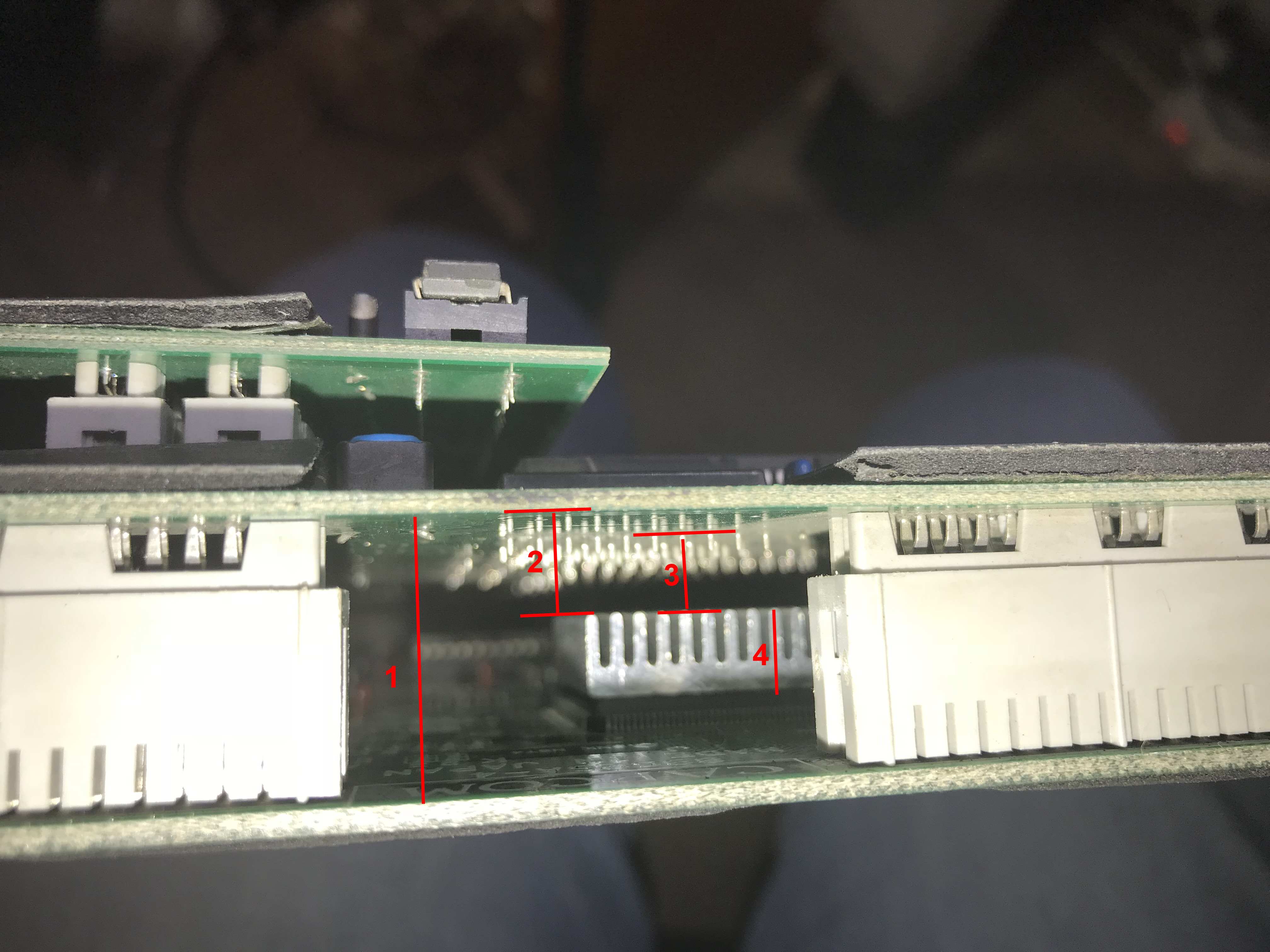
1) Distance between A and B boards: 19 mm
2) Distance from top of heat-sink to B board PCB: 7 mm
3) Distance from top of heat-sink to tip of soldered pins of upper components: 5 mm
4) Height of heat-sink: 8 mm
My measurements are rough but within error margin of 1mm
Since we are talking about A boards, here is a funny thing for you A complete 100% bootleg CPS1 A board 
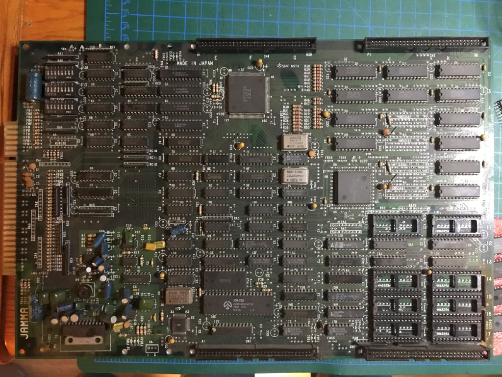
And the bootleg CPS-A-01 asic...
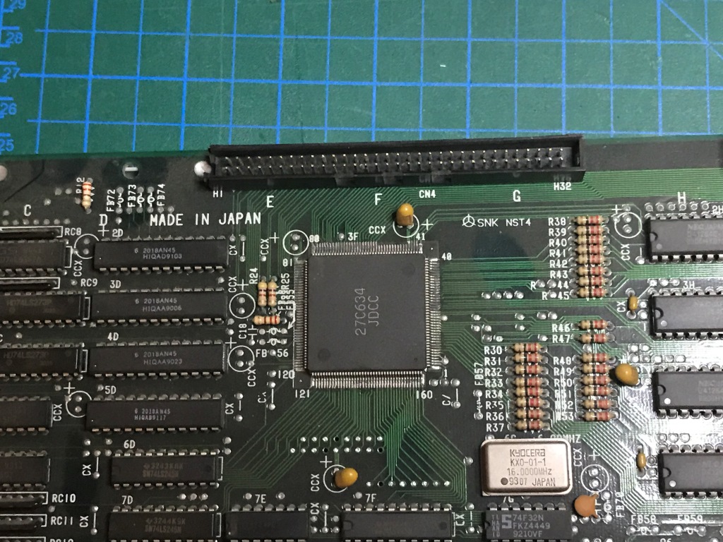
It is hard to believe that someone took the necessary time & effort to reproduce these back in the day...
It is not working though but I'll try the ASIC in one of my cps1 A boards...
A complete 100% bootleg CPS1 A board
And the bootleg CPS-A-01 asic...
It is hard to believe that someone took the necessary time & effort to reproduce these back in the day...
It is not working though but I'll try the ASIC in one of my cps1 A boards...
xodaraP
Legendary
I haven't seen that A custom before, but there's one that's appeared before labelled COMCO
I wonder if the bootleggers did reproduce it or if they just managed to "obtain" the ASICs before they were silkscreened?
If it was reproduced it would be great to get the reproduced versions looked at by someone who knows about these things to see how it was done/if it would be possible to do it again
I cannot comment specifically on these custom chips used on CPS1-A board, as I really have no idea how they work.Man, I always wonder if the A board in these could be reproduced with modern electronics.
Paging @brizzo, do you have any info that you could share on this topic.
But yes in theory just about any pcb can be reproduced with custom parts, just depends how much you want to invest
we got about 2 grand and a punisher board, would that get it done?I cannot comment specifically on these custom chips used on CPS1-A board, as I really have no idea how they work.Man, I always wonder if the A board in these could be reproduced with modern electronics.
Paging @brizzo, do you have any info that you could share on this topic.
But yes in theory just about any pcb can be reproduced with custom parts, just depends how much you want to invest


