I usually use 104 (0.1uF) ceramic caps. From what I understand ceramic caps work better for this as they have better response time. This is also what is used for the original ROMs on these and many other PCBs; I wouldn't use Captain Gluegun's work as a reference as he's clearly just grabbing whatever he has laying around.
You are using an out of date browser. It may not display this or other websites correctly.
You should upgrade or use an alternative browser.
You should upgrade or use an alternative browser.
- Thread starter 98pacecar
- Start date
")
nevermind boys, i thought it was rotated the other way around. nothing to see here!
Last edited:
nearly all vertical games have a screen flip option as it is. There are some that don't but it's pretty uncommon for it to not be included.
Do you print these? Would be willing to pay for some nice labels. I don’t have access to a nice printer.Revised labels in PDF format.
I've reduced the horizontal size which should make for a perfect fit.
Also revised the Ketsui label because as @SpudJones pointed out I had the last two characters reversed
@oneleaf86 those look excellent!Revised labels in PDF format.
I've reduced the horizontal size which should make for a perfect fit.
Also revised the Ketsui label because as @SpudJones pointed out I had the last two characters reversed
Can you crosspost them here as well so they can be easier found?
Artwork scans for cabs/games
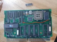
Thank you very much.Here's mine:Can someone post photos of the ddp2 prog pcb ? ( 0354-01-FN )
it actually looks very similar to the PCB-0333-03 used by KOV2
the other side and gfx board just for the sake of completeness:


No missing component.
I'm surprised the crystal is not present in U2.
Since, as documented, it's a type 2 protection supposed to run portions of the game...
I will try to replace the ram chips to see if it can solve the problem ...
This PCB is also very similar to PCB-0349-01-FL (PRG) - Dragon World 2001
which I'm more likely to "sacrifice" than DDP2
I would check connections on all the buffers and level shifters as well, and maybe check the EPROMs for bit rot.
While I can't promise a timeline, I'll probably start the layout of the gfx board next week. I've got a KOV2 cart on the way, which should arrive sometime later this month. While I don't expect any major surprises for the gfx board it'll be interesting to map out the prg board.
While I can't promise a timeline, I'll probably start the layout of the gfx board next week. I've got a KOV2 cart on the way, which should arrive sometime later this month. While I don't expect any major surprises for the gfx board it'll be interesting to map out the prg board.
Top3000 will do the trick. More discussion can be found here: Best, low cost, programmer for most arcade hobbyists to have???[.4046/url]A little of topic. What is a good programmer to get if I want to re write coode on the eeprom for the white/black label. Since I have a black label on its way already
@ratsflif I have €20 here sitting in paypal to make this happen. Any luck getting this dumped?Hello all,
Just registered so I could contribute.
I can confirm that same sprite glitch on Espgaluda when you do a large bullet cancel.
I have the same issue with the Backgrounds disappearing on Ketsui and Espgaluda, Sheep Nova was super fast in response and is sending out the two replacement chips, so I'll report back once installed.
And, I have the DDP DOJ pgm cart with both black/white, both versions work perfectly, I received it about a year ago from arcademodbios.
we haven't figured out Killing Blade yet. KOV2 is still the only cart we know how to convert to Espgaluda and Ketsui.so now when Killing Blade can be used, anyone care to sell me a Knights of Valour 2 - Nine Dragons? (I will NEVER use it for any conversion, I want to play it since I love the series)
If you want a KOV2ND ask @sheep_nova he regularly gets them in stock.
andynumbers
Professional
I ended up fixing this problem. It was the volume pot. I ended up using this replacement on Amazon: https://www.amazon.com/gp/product/B07JM3RSMB/ref=oh_aui_detailpage_o00_s00?ie=UTF8&psc=1I got my Sheep Nova carts the other day.
One of my PGM motherboards I got from him has a "hiss" in the sound that is always present, even when the game is silent. Also, when the volume knob is all the way to minimum, sound/music will still be heard. Normally it should be muted at the lowest volume setting.
I have already tried to fix these problems by replacing all of the electrolytic capacitors on the PCB. No effect. Also tried cleaning the volume pot with rubbing alcohol and that didn't do anything.
Any ideas? Maybe a bad preamp chip or audio amplifier?
You'll have to make a small modification. The original pot is 3-pin and this is 5-pin. Clip off the two outside pins since you won't need them. When you desolder the old pot, you'll notice there's a lower pin that holds the pot in place. This won't be present on the new pot (and you'll have to clip off the two side support pins since they get in the way), so you'll have to manually add a jumper wire to tie this to the center pin on the motherboard.
If anyone else attempts this and needs pictures, let me know. It's pretty straightforward.
A year ago, I compared an original ketsui PCB with the ketsui convert cartridge, and I noticed that the sound was too loud (saturated) on the convert cart.
Last month I checked my Demon Front PCB, and noticed that the sound VR (potentiometer) was a 10K VR on the single PCB, and regular PGM slot has a 1K VR potentiometer.
Could it be the cause of the sound issue ?
Did someone try to replace the 1K VR pot by a 10K VR pot on a regular PGM slot and test the cave sounds ?
sheep_nova
Grand Master
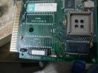
Both of the 2 pcs picture^+^,do keep the wire disconnected.(the black pencil we marked)
Picture 1,soldering like that(we mark with red pencil),and also exchange the encrypted IC.It should be able to solved.
Picture 2 ,exchange the encrypted IC,also keep the wire disconnected.
If still have some other question,pls let me know.
Picture 1,soldering like that(we mark with red pencil),and also exchange the encrypted IC.It should be able to solved.
Picture 2 ,exchange the encrypted IC,also keep the wire disconnected.
If still have some other question,pls let me know.
Attachments
KalessinDB
Grand Master
This is for the background tile fix you're sending out? We have to disconnect the wire (and maybe add another one)? Or is this for a different fix?Both of the 2 pcs picture^+^,do keep the wire disconnected.(the black pencil we marked)
Picture 1,soldering like that(we mark with red pencil),and also exchange the encrypted IC.It should be able to solved.
Picture 2 ,exchange the encrypted IC,also keep the wire disconnected.
If still have some other question,pls let me know.
Excuse me, but what do you mean when you say “Encrypted IC”? Is that TTL chip you removed in the first picture? Did you replace it with another one placed in the socket in the top-left of the first image?Both of the 2 pcs picture^+^,do keep the wire disconnected.(the black pencil we marked)
Picture 1,soldering like that(we mark with red pencil),and also exchange the encrypted IC.It should be able to solved.
Picture 2 ,exchange the encrypted IC,also keep the wire disconnected.
If still have some other question,pls let me know.
