What's new

codecrank

Professional
Joined
May 24, 2016
Messages
201
Reaction score
333
we have an arcade at work, ~20 candy cab on freeplay, how do I know when to change games ? well this should help me :D

The idea is to monitor start buttons being pressed, and to either push or pull the data over a wireless network. it has to be cheap, easy to add to cabs, and somewhat reliable.

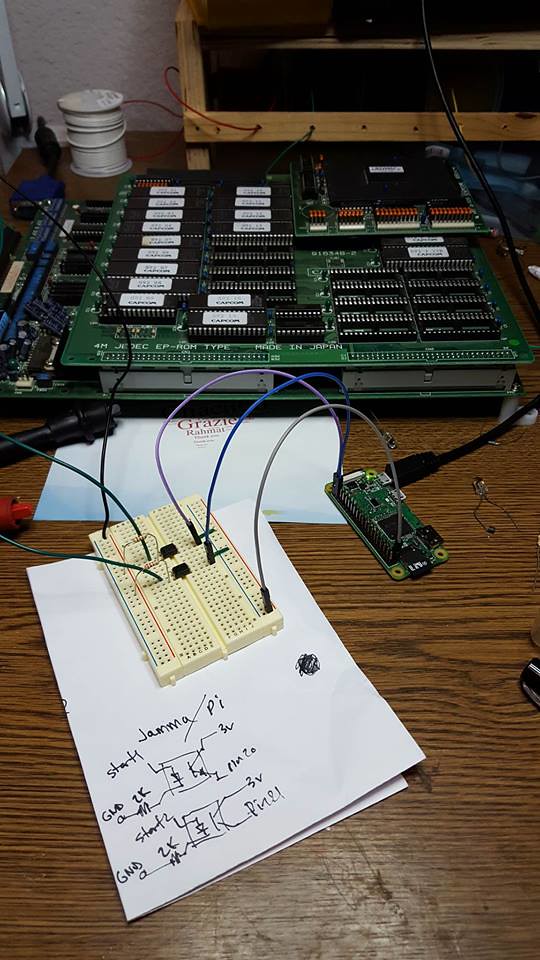
so first a prototype, the pi zero is 10$. so far so good.
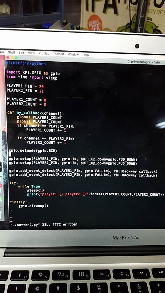
39966143222_bc6816742d_b.jpg


simple code

39997426321_592eb746ef_b.jpg


turned into a pi zero hat , pinout is Start , 5v ( to power the pi ) , Gnd . maybe ~5$ worth of part, that's fine, but making the pass-through adatper is time consuming, I don't want to have to make tons of them, plus what about a versus city ? I could do a jamma pass-through adapter instead , but it won't work for JVS games , oh the dilemma.

25127087017_8fcd4d45d4_b.jpg


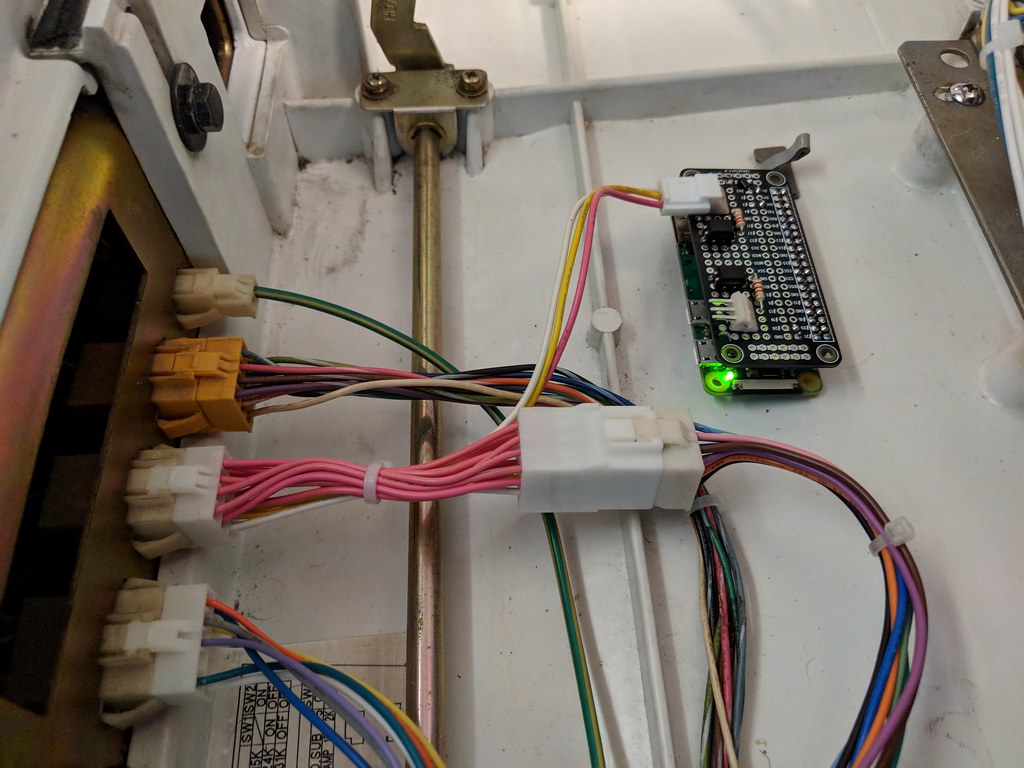
And it looks like we have a working proof of concept :D


Next is deciding how I want to store the data locally, push / pull, central data visualization, etc . I tried the googledoc spreadsheet api and it's utter garbage, slow as hell.

more to come...
 
I was thinking about doing exactly this, even bought some ESP8266 boards to do the data collection, just never got around to working on it.

I'm interested to see where this project goes.

the problem with the Pi Zero W is that they're difficult to source in bulk. the ESP8266 modules are just as easy to program for and are cheaper and easier to source in bulk, though shortly after I bought them the Realtek RTL8710 modules came out which are supposedly better in every way.

for the pass-through adapter I would recommend building them based on the quick disconnects used on the buttons, you can get a terminal splitter like this (but in the appropriate size):
F7197221-01.jpg


that make the only headache wiring the power though I think most Sega candy cab should have a 4-pin JST NH header for 5V readily available.
 
Last edited:
oh that's neat. yeah 5v.. JVS like the naomi/nc/etc cabs have the 5v out on the io. but we mostly have blasts and astros and versus cities. hence why I'm tempted to do the jamma passthrough. that would work with the jvs/jamma converter. wifi should work ok from inside the cab. no aeros :D

also those connectors means I have to run long ass wires in the VS cabs.

but the jamma passthrough adapters would be the most expensive for of the units lol. Most importantly, the time to make 20 of them ... anyone wants extra $ ? :D
 
I've wanted to do the same type of thing for the expo I run. Knowing which games are getting play, but more importantly, determining if certain games may have an issue quickly is of great value.

The other thing I'd planned on including is a way to do free play for the games that don't have a built in option.

A couple of implementation questions: I see you're using rpi.gpio. Is there a reason you chose that over pigpio? I read somewhere that rpi.gpio has been deprecated, but is still available. Also, what device are you using to handle the level shifting? I assume that's what the chip and resister are doing.
 
The other thing I'd planned on including is a way to do free play for the games that don't have a built in option.
there was a guy on KLOV who built something to do that. it's basically a button rigged up to the coin switch, but it has a circuit that makes you wait 20 seconds or so before it will register another coin drop. the idea being that they don't want people just just hammer the button to rack up credits and then walk away from the machine while it sits there burning an image in the monitor (since having credits available often bypasses the attract mode).


I see you're using rpi.gpio. Is there a reason you chose that over pigpio?
FWIW I recently used pigpio for an application at work, pulling sensor data on a test rigs that can run non-stop for up to weeks at a time. We've been using them for a few months now and so far it's been really reliable, we have had other problems but the pigpio library hasn't been one of them.
 
A couple of implementation questions: I see you're using rpi.gpio. Is there a reason you chose that over pigpio? I read somewhere that rpi.gpio has been deprecated, but is still available. Also, what device are you using to handle the level shifting? I assume that's what the chip and resister are doing.
All the tutorials and examples I read used rpi.gpio , hence I used that

what do you mean by level shifting ? the chips are optical couplers, so I could mix the jamma 5v circuits and the 3v gpio circuits. Maybe now what they use a common ground, I could use a voltage divider, but this works and is safer. Resistors are simply to limit the current to the least amount needed to operate the optocouplers.
 
I was wondering how you were handling matching the 3.3v gpio to the 5v button. I wasn’t aware of opti couplers. I’ve always used a pre built level shifter board to do the same thing. I think your way is a lot better!
 
Back
Top