Weird, this quote was meant for the wtf sales post thread. Not sure why it quoted this instead and it got here. Disregard.Yup, the Japanese one is the newer and with most fixes and balance changes.
Last edited:
Weird, this quote was meant for the wtf sales post thread. Not sure why it quoted this instead and it got here. Disregard.Yup, the Japanese one is the newer and with most fixes and balance changes.
they probably "standardized" on the short a-board, and then when CE came out and they wanted more speed they changed to 12MHz . the PCB is the same between the short and the dash board, it's literally just a change in the value of some components.If you're producing a new revision of boards it would make sense to standardize at the base level which to me would be when CPS-B-21 was introduced with regards to the dash A board.
Totally, this is was around the time of the short 10mhz A-board's.they probably "standardized" on the short a-board
Do you have a photo/video of what you mean?One thing I notice with regards to the A board revisions in SF2CE/HF is if you use the 10MHz board the startup rom checks are always garbled before completing and then show properly. On a dash board the text is always correct. That to me seems to be a good indicator of which board should mate with which however I don't have any other games to verify this theory.
Yea that's what I was thinking, only make the switching automatic decided by the ROM selected to load.A small PCB with both crystal speeds and a switch won't work?
")
SIgh, I was hoping this wasn't the case, but, yeah, there it is.Just tested few more games on a DASH motherboard and found 1941 plays overspeed.
It obviously means a multi would need two different A boards (10MHz and 12MHz) to play games correctly OR a way has to be found to switch between the two frequencies (by modding the A board to accept an external CPU clock for instance).
I was thinking of generating two clocks with the ARM on the multi and send the clock signal corresponding to the game.SIgh, I was hoping this wasn't the case, but, yeah, there it is.
Anyway, you just need two oscillators, one at 12Mhz and one at 10Mhz and a switch or, better, a relay. Then the multi can send an impulse to switch the relay on 10Mhz or 12Mhz oscillator depending on the ROM loaded.
If the ARM is on the B board and the oscillator is on the A board how are you going to accomplish that ?I was thinking of generating two clocks with the ARM on the multi and send the clock signal corresponding to the game.No oscillator, no relay or switch, all made with logic.
Of course A board would have to be slightly modified (like cutting the trace from the OG oscillator and reroute it to the B board).If the ARM is on the B board and the oscillator is on the A board how are you going to accomplish that ?I was thinking of generating two clocks with the ARM on the multi and send the clock signal corresponding to the game.No oscillator, no relay or switch, all made with logic.
Yup that's also what I prefer.I'd be ok desoldering the osc and soldering a wires or a connector in place. I would NOT be ok with cutting a trace. The ability to "Undo" the modification like nothing happenes is important to me, and I'd suspect others as well.
We're talking about only 12Mhz, of course an insanely long distance could be an issue but in this case I was thinking of moving the oscillator by only a centimetre as the daughterboard would fit at the place the oscillator was.One question/concern I have is whether moving the crystal physically off of the A-Board will have any affect on the signal it produces? I know with some components their physical distance from the chip they are serving can impact the performance, so i don't know if that's something that needs to be taken into account.

Is this what you are talking about? My Hyper Fighting does this for the briefest of moments on boot up. You need to frame scrub to even catch it. Tested on a couple of boards that have 12Mhz A boards and it seems to be normal.One thing I notice with regards to the A board revisions in SF2CE/HF is if you use the 10MHz board the startup rom checks are always garbled before completing and then show properly. On a dash board the text is always correct. That to me seems to be a good indicator of which board should mate with which however I don't have any other games to verify this theory.
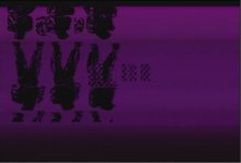
Same board, swap in CE ROMs and it boots perfectly.I've got some input that may or may not be useful, that ties in with talk of relocating the crystal and with the above images.
I found some cables that allow separation of the A and B board, so I can more easily work on troubleshooting a no audio issue on a 10mhz A board. The cables are about 2 feet in legth. I've checked continuity on every single pin of the 4 connectors and all are good. Powering the board gets stuck at the screen on the left, with the upside down character sprites (no text).
Not looking for help on my problem, and I haven't taken it past confirming connections are good on all pins, but wanted to offer the observations since it seems applicable to the discussion.
Cables shouldn't be an issue. I've built a set (4 flat cables with connectors at the ends) myself to help me in my repairs, lenght is ~50cm and never had any issue.I've got some input that may or may not be useful, that ties in with talk of relocating the crystal and with the above images.
I found some cables that allow separation of the A and B board, so I can more easily work on troubleshooting a no audio issue on a 10mhz A board. The cables are about 2 feet in legth. I've checked continuity on every single pin of the 4 connectors and all are good. Powering the board gets stuck at the screen on the left, with the upside down character sprites (no text).
Not looking for help on my problem, and I haven't taken it past confirming connections are good on all pins, but wanted to offer the observations since it seems applicable to the discussion.