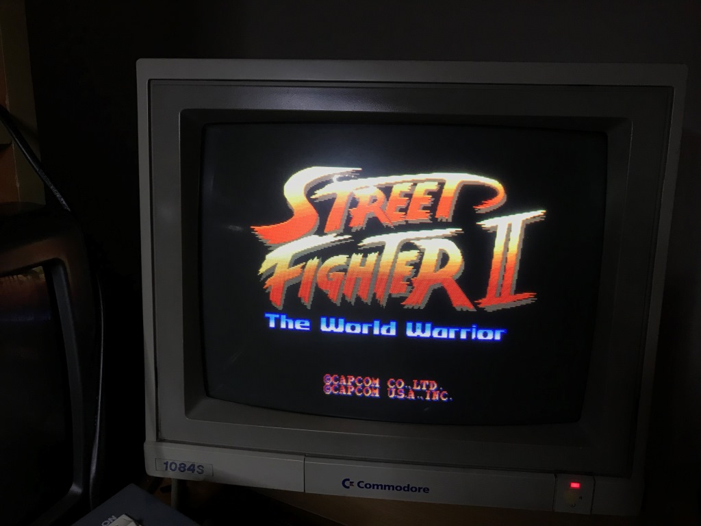
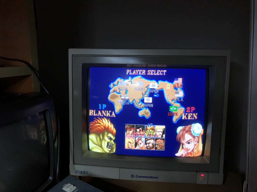
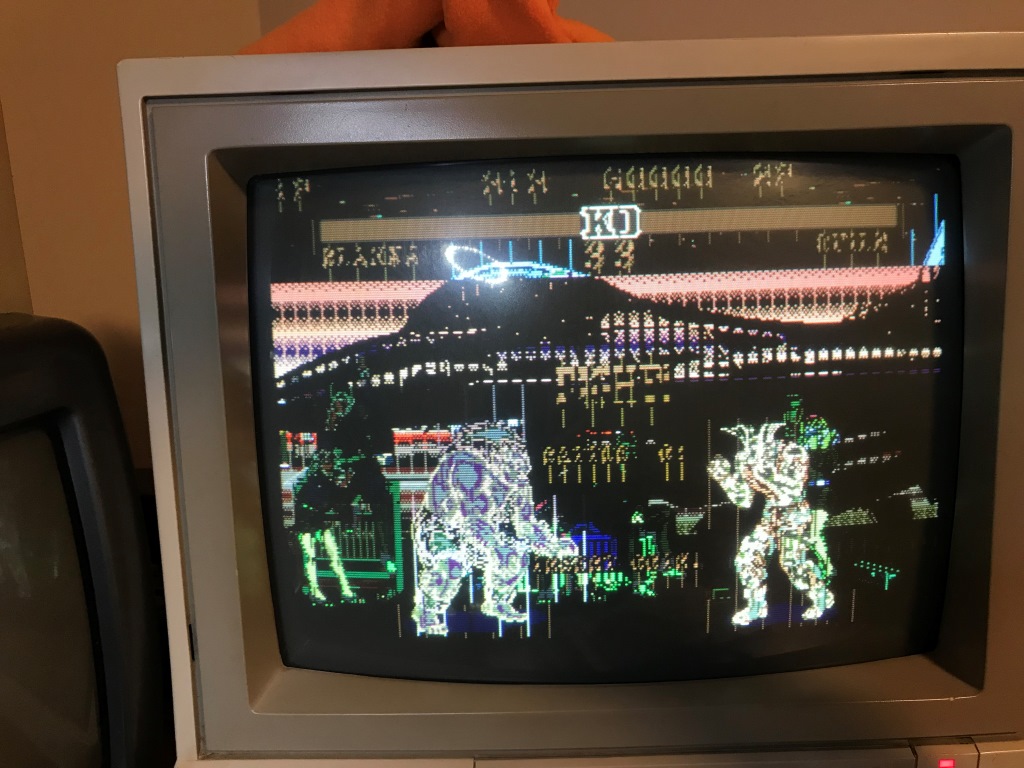
Remember the Street Fighter II: World Warrior PCB I mentioned about last week?
Turns out to be my other WW had issues more than just wrong dip switch settings.
Anyway, I ended up having no working WW PCB") and I decided to fix the first WW which I shelved as spare parts.
and I decided to fix the first WW which I shelved as spare parts.
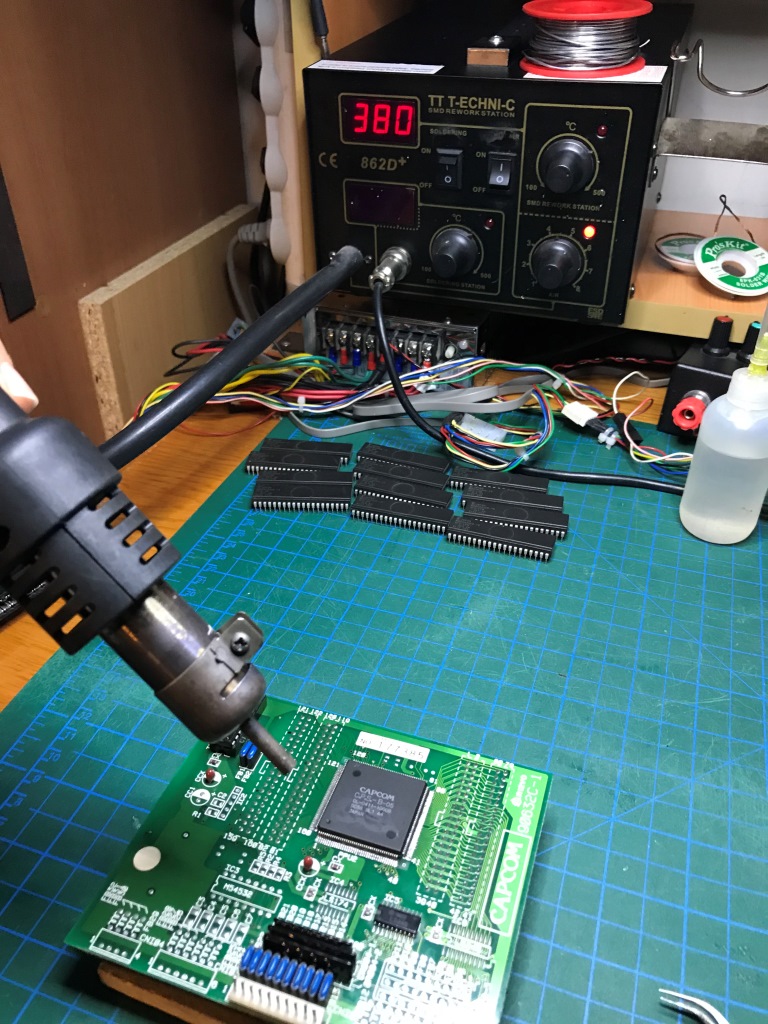
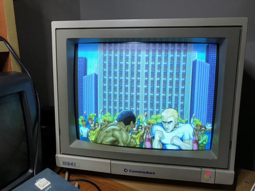
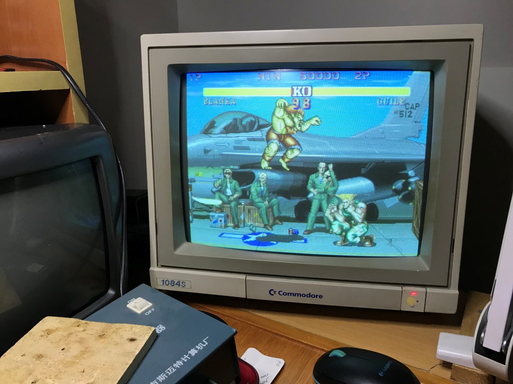
I've narrowed the problem to the C-board by swapping aorund A B C boards and testing. Also @Apocalypse helped providing evidence that the culprit for such a massive graphics glitch is most likely is the PPU2 itself.
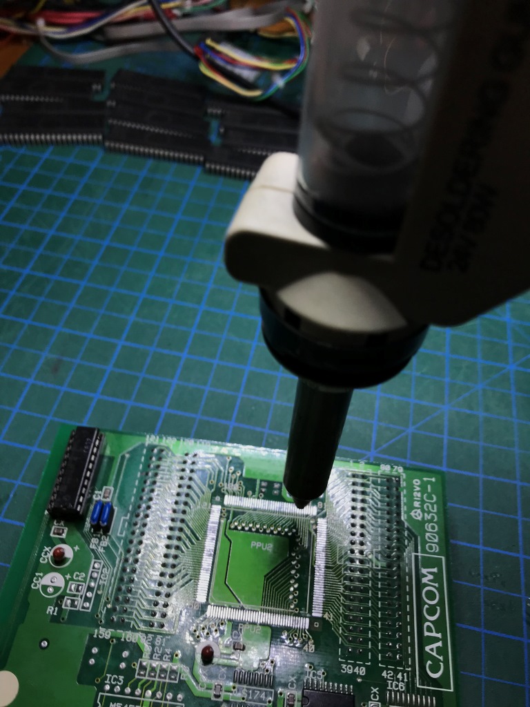
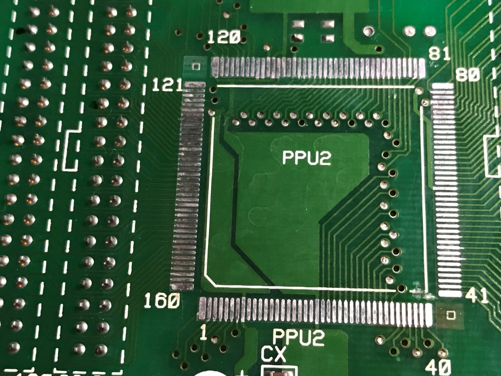
Still, for a last resort, I've checked ALL the legs of the PPU2 for bad solder points and tested ALL the continutiy from the legs to the C-board connector pins. All checked OK. Moreover, I've tested ALL the signals (from the connector pin tips) with my oscilloscope and didn't find any "funny" looking signals either. Yes there were some pins stuck to either GND or 5V but don't have any info if they are valid signals or not. Just didn't noticed anything floating between 0-5V.
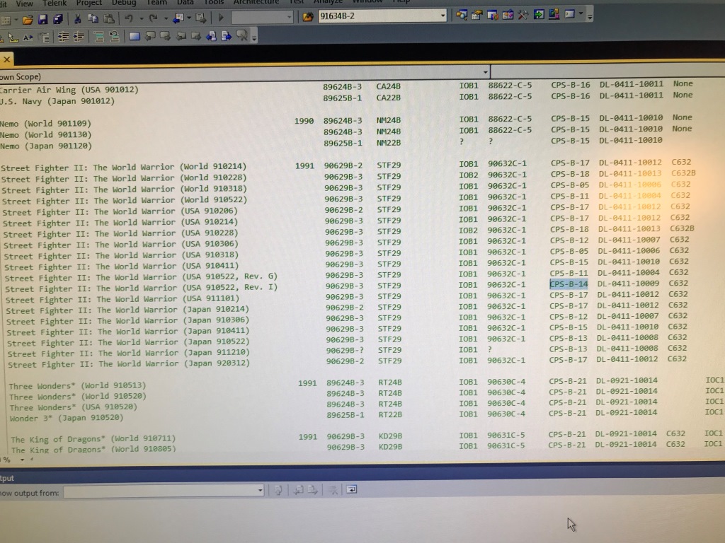
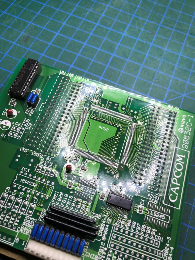
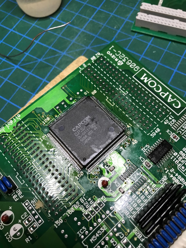
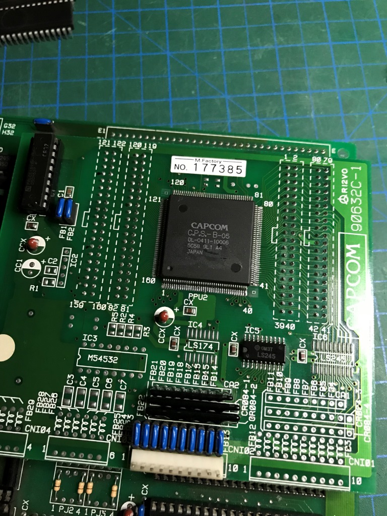
Anyway, after ruling everything out, its time to replace the suspect PPU chip. Which was a CPS-B-05 model;
Now, where to find a replacement for that?
Option A: Use the CPS-B-21 from my spare part CPS2 A board
As @Apocalypse mentioned in one of his writings the 21 has some differences that won't fit to my current C board pin-by-pin. Need another PAL hanging around and also need a "modified" WW program rom set which is compatible with 21 which does not exists in official capcom releases.
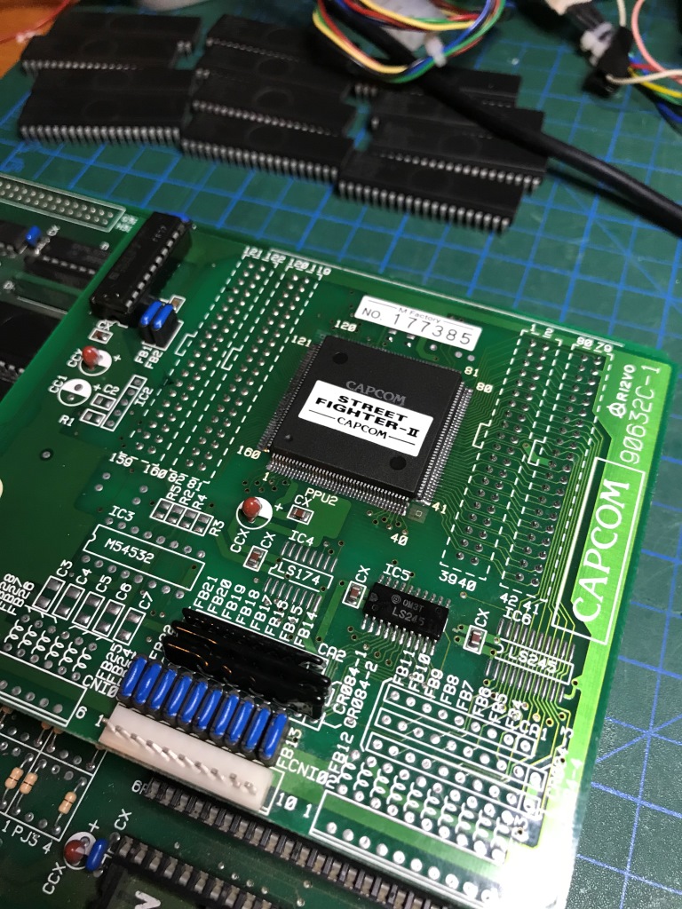
Option B: Find another C board PPU from my collection that I should be comfortable to sacrifice the game and must have a compatible rom set release.
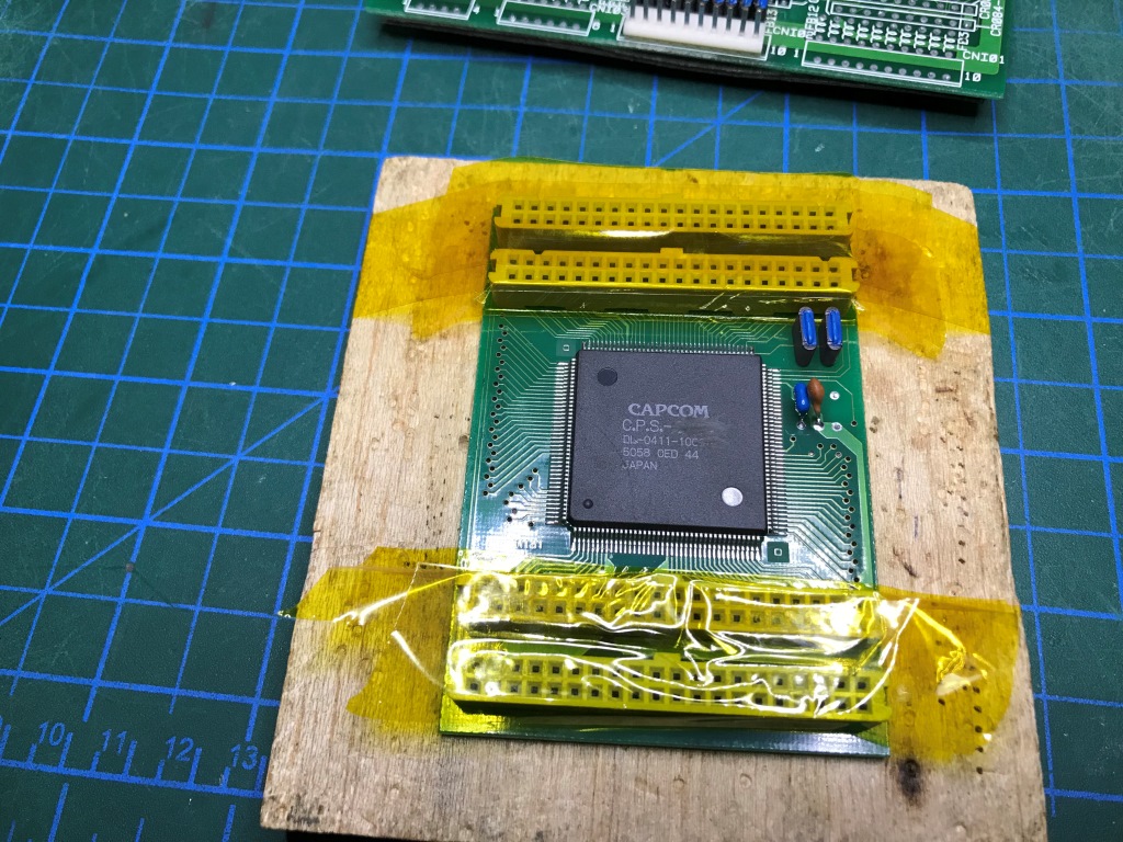
After going through my "bootleg" and "hack/conversion" pile, I found this:
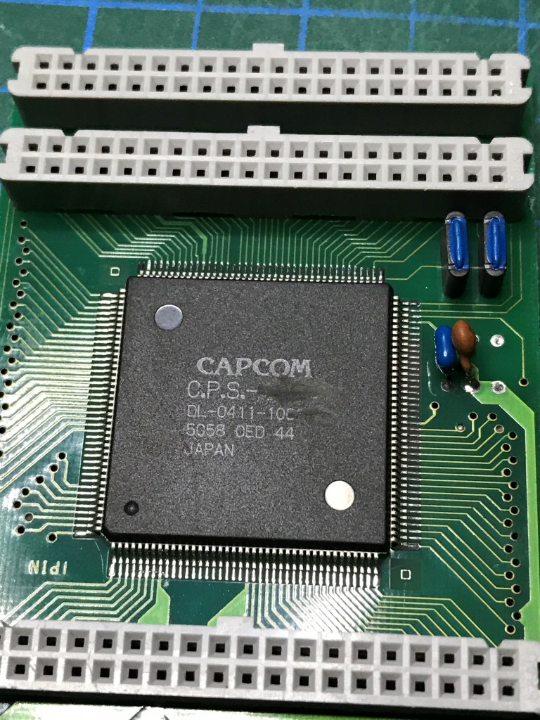
This is a C-Board from my Chinese bootleg Cadillacs & Dinasours. The hack was based on a 100% bootleg B-board with a PIC microcontroller and although the game graphics were OK without any obvious glitches, the music loop was extremely nerve breaking... Never put this in a cabinet and never had a plan to either play it or sell it. Afterall I've purchased it very cheap and was planning to use it as a spare part and now the time has come")
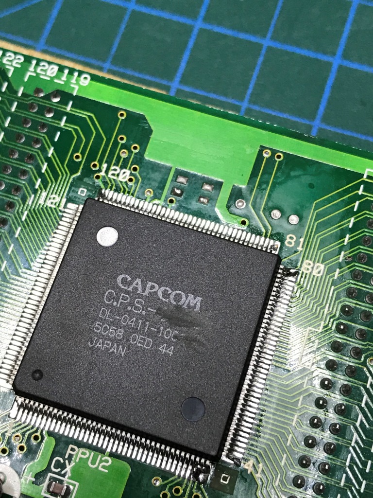
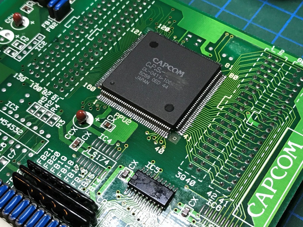
It is a 88622-C-5 type C-board and main problem with this C-board was the bastard bootlegger back-in-the-day has scratched the PPU model number to protect his secret
Turns out to be my other WW had issues more than just wrong dip switch settings.
Anyway, I ended up having no working WW PCB
and I decided to fix the first WW which I shelved as spare parts.I've narrowed the problem to the C-board by swapping aorund A B C boards and testing. Also @Apocalypse helped providing evidence that the culprit for such a massive graphics glitch is most likely is the PPU2 itself.
Still, for a last resort, I've checked ALL the legs of the PPU2 for bad solder points and tested ALL the continutiy from the legs to the C-board connector pins. All checked OK. Moreover, I've tested ALL the signals (from the connector pin tips) with my oscilloscope and didn't find any "funny" looking signals either. Yes there were some pins stuck to either GND or 5V but don't have any info if they are valid signals or not. Just didn't noticed anything floating between 0-5V.
Anyway, after ruling everything out, its time to replace the suspect PPU chip. Which was a CPS-B-05 model;
Now, where to find a replacement for that?
Option A: Use the CPS-B-21 from my spare part CPS2 A board
As @Apocalypse mentioned in one of his writings the 21 has some differences that won't fit to my current C board pin-by-pin. Need another PAL hanging around and also need a "modified" WW program rom set which is compatible with 21 which does not exists in official capcom releases.
Option B: Find another C board PPU from my collection that I should be comfortable to sacrifice the game and must have a compatible rom set release.
After going through my "bootleg" and "hack/conversion" pile, I found this:
This is a C-Board from my Chinese bootleg Cadillacs & Dinasours. The hack was based on a 100% bootleg B-board with a PIC microcontroller and although the game graphics were OK without any obvious glitches, the music loop was extremely nerve breaking... Never put this in a cabinet and never had a plan to either play it or sell it. Afterall I've purchased it very cheap and was planning to use it as a spare part and now the time has come
It is a 88622-C-5 type C-board and main problem with this C-board was the bastard bootlegger back-in-the-day has scratched the PPU model number to protect his secret
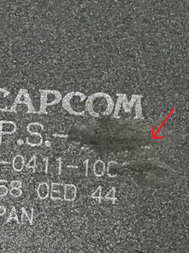
 look where the red arrow points) It seems to be the last remainder of a "4"