Paranoid_Andy
Enthusiast
Hey all.
I have been looking for a tutorial for how to setup the multi to use key writing but I can't seem to find anything. I have a pdf guide on how to initially setup the kit called 'Instructions_CPS2_Multi_Boot_v2.pdf' and a video tutorial from Mitsurugi called 'Walsdawg Arcade Preparing your CPS2 B-board for Darksoft s Multi-kit'. However I didn't see key writing and the "4 wires" mentioned in them.
I did find 'Darksoft s CPS2 Multi now Restores keys!' video but that seems to be more of a showcase rather than a step by step tutorial so I'm not sure if there is more to it than just attaching 4 wires. Hard to see where they are attached as well.
If there is no guide on this, then is there a guide on how to add more ROMs to the Avalaunch pack? I have that working at the moment, but I noticed it's missing several games. I'd like to add them but I don't know how because everything seems to be using the keys method instead.
Thanks!


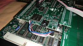
 ^ that's it
")
 Think I got it mostly taken care of now.
 )
)