Heh. Yeah, it's not like the Naomi, which won't boot some games without the right I/O board (like Ninja Assault).I now realize how silly of a question that is since it doesn't care about it with any other game... T_TAll you need is to have a Namco, Sega, or Capcom I/O attached to the 256 and Taiko will boot into the game. It doesn't look for any type of controller being actually attached to the I/O.I'm curious to know if the 256 is fine booting Taiko with just a single drum attached. Have you got just the one in your setup, Defor?
You are using an out of date browser. It may not display this or other websites correctly.
You should upgrade or use an alternative browser.
You should upgrade or use an alternative browser.
- Thread starter rewrite
- Start date
If it were so simple...Heh. Yeah, it's not like the Naomi, which won't boot some games without the right I/O board (like Ninja Assault).
Ridge Racer V needs force feedback properly wired up
Battle Gear 3 needs Taito "JVS I/O PCB" and apparently no substitutes
Battle Gear 3: Tuned also needs Taito "JVS I/O PCB"
All the touchscreen games need a card reader connected to the serial port on the front of the system (this can sometimes be bypassed)
Cobra is more or less JVS agnostic as long as there's an
 Y analog input pair, but it also wants a serial port unless certain checks are bypassed in the settings first.
And then there's Wangan Midnight R and Wangan Midnight that appear to work, but simply stop responding fast, possibly due to a low RAM cache issue (Still needs testing)
Yes, I normally only use one drum, but unless you ground the analog inputs for the second drum (or connect a second analog device), the analog inputs are floating, and will act as repeated drum hits.I'm curious to know if the 256 is fine booting Taiko with just a single drum attached. Have you got just the one in your setup, Defor?
So new development of the day....
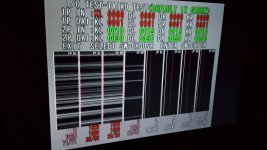
Battle Gear 3 booting...
Not yet running, "HANDLE ERROR"
not entirely sure why it's working now...
more research is needed, but clearly, the Taito PCB is unnecessary.
Battle Gear 3 booting...
Not yet running, "HANDLE ERROR"
not entirely sure why it's working now...
more research is needed, but clearly, the Taito PCB is unnecessary.
Last edited:
I'd always wondered why I had been getting random drum hits when I'd tried wiring up buttons to Taiko. Never thought that it was the player 2 side causing that. >_>Yes, I normally only use one drum, but unless you ground the analog inputs for the second drum (or connect a second analog device), the analog inputs are floating, and will act as repeated drum hits.I'm curious to know if the 256 is fine booting Taiko with just a single drum attached. Have you got just the one in your setup, Defor?
Defor, since the PS2 Taiko controller only has two wires for each of the four sensors (GND and Input), it's not possible to wire those directly to an I/O board (via Mitsurugi-W's JVS Helper PCB) is it?
I'm guessing you need something like an Arduino Mini to convert the Playstation 2's drum controller hits from digital to analog...?
Pictures of what the inside of a PS2 Taiko controller looks like, for the curious:
http://psx-scene.com/forums/f110/taiko-drums-taiko-series-hardware-questions-110563/#post1041843
well, if you think about it, you can bypass the ps2 control board entirely- you've got analog sensors sitting right there.Defor, since the PS2 Taiko controller only has two wires for each of the four sensors (GND and Input), it's not possible to wire those directly to an I/O board (via Mitsurugi-W's JVS Helper PCB) is it?
I'm guessing you need something like an Arduino Mini to convert the Playstation 2's drum controller hits from digital to analog...?
this is the same method you'd use with the arcade drums.. I'll see if I can draw up some simple schematics before the end of the weekend- sorry, a bit dead at the moment- was up until 5AM version testing (199) 246/256 game dumps
")
Oh, so using the JVS Helper PCB, you would just run those sensors to AD0/AD1/AD2/AD3, split the 4 GND wires between the 2 GND's going into the Helper PCB', wire the Start button, and wire Select as Coin?well, if you think about it, you can bypass the ps2 control board entirely- you've got analog sensors sitting right there.Defor, since the PS2 Taiko controller only has two wires for each of the four sensors (GND and Input), it's not possible to wire those directly to an I/O board (via Mitsurugi-W's JVS Helper PCB) is it?
I'm guessing you need something like an Arduino Mini to convert the Playstation 2's drum controller hits from digital to analog...?
this is the same method you'd use with the arcade drums.. I'll see if I can draw up some simple schematics before the end of the weekend- sorry, a bit dead at the moment- was up until 5AM version testing (199) 246/256 game dumps
First off, connect each AD pin with a 10 kΩ resistor connected to AVCC.
AD0 -- 10 kΩ -- AVCC
AD1 -- 10 kΩ -- AVCC
AD2 -- 10 kΩ -- AVCC
AD3 -- 10 kΩ -- AVCC
AD4 -- 10 kΩ -- AVCC
AD5 -- 10 kΩ -- AVCC
AD6 -- 10 kΩ -- AVCC
AD7 -- 10 kΩ -- AVCC
AD8 -- 10 kΩ -- AVCC
This will serve as two purposes.
1) to pull the AD inputs high when not connected to a drum, thus eliminating the random drum hits.
2) to provide a positive reference voltage, but no current, to oppose the drum output which serves as a 2-pole variable resistor to ground.
Now we need to connect the drum inputs- you might have to swap them around to match the pinout of your drum.
Drum 1 output 1 -> AD0
Drum 1 output 2 -> AD1
Drum 1 output 3 -> AD2
Drum 1 output 4 -> AD3
Drum 2 output 1 -> AD4
Drum 2 output 2 -> AD5
Drum 2 output 3 -> AD6
Drum 2 output 4 -> AD7
Then you'll need to connect the grounds from each drum to AGND.
Drum 1 GND 1 -> AGND
Drum 1 GND 2 -> AGND
Drum 1 GND 3 -> AGND
Drum 1 GND 4 -> AGND
Drum 2 GND 1 -> AGND
Drum 2 GND 2 -> AGND
Drum 2 GND 3 -> AGND
Drum 2 GND 4 -> AGND
From here, you can wire up the rest of the digital IO as a service panel (this is the suggested configuration):
COIN (SPST Pushbutton)
TEST (SPST Pushbutton)
SERVICE (SPST Toggle)
UP/DOWN (SPDT Momentary)
ENTER (SPST Pushbutton)
You WILL want to wire up a service panel in order to set the analog thresholds for the drums.
Pretty sure I've explained this all correct...
Aaaah. So THIS is why I had some problems. It was driving me mad, even though I have temporarily stopped working on my Taiko cabinet in favor of other projects. Thank you so very much, this is the final piece of the puzzle for meYes, I normally only use one drum, but unless you ground the analog inputs for the second drum (or connect a second analog device), the analog inputs are floating, and will act as repeated drum hits.

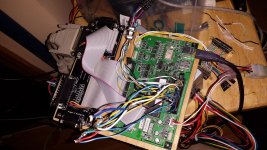
Have run into a it of a hitch with my Taiko PS2 drum build when trying to run it via a S-JIHP Helper PCB and Sega I/O:
S-JIHP: Sega JVS I/O Helper PCB
S-JIHP: Sega JVS I/O Helper PCB
Taiko Drum build update (Jan 19):
Still no luck getting the Player 1 side of Taiko no Tatsujin to be playable as I'm still getting auto-firing drum hits. But I made some progress.
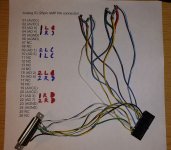
I took a 26pin AMP RA Connector and, through trial error, managed to figure out the JVS analog mapping that a Taiko drum used on the Namco 246/256. I was also able to finally fully ground the Player 2 side and that is silent and no longer fires on its own. As I mentioned, I can't seem to get the Player 1 side to stop auto-firing. (It will stop if you ground the inputs, but that's not the goal.) I may just have my Taiko drum controller hooked up wrong, but I'm at a loss for how to proceed at this point. Ideas?
Helpful info:
The JVS button mapping for Taiko no Tatsujin is as follows...
AD0 = player 1 left drum
AD1 = player 2 left rim
AD2 = player 2 left drum
AD3 = player 1 right drum
AD4 = player 1 right rim
AD5 = player 1 left rim
AD6 = player 2 right rim
AD7 = player 2 right drum

Still no luck getting the Player 1 side of Taiko no Tatsujin to be playable as I'm still getting auto-firing drum hits. But I made some progress.
I took a 26pin AMP RA Connector and, through trial error, managed to figure out the JVS analog mapping that a Taiko drum used on the Namco 246/256. I was also able to finally fully ground the Player 2 side and that is silent and no longer fires on its own. As I mentioned, I can't seem to get the Player 1 side to stop auto-firing. (It will stop if you ground the inputs, but that's not the goal.) I may just have my Taiko drum controller hooked up wrong, but I'm at a loss for how to proceed at this point. Ideas?
Helpful info:
The JVS button mapping for Taiko no Tatsujin is as follows...
AD0 = player 1 left drum
AD1 = player 2 left rim
AD2 = player 2 left drum
AD3 = player 1 right drum
AD4 = player 1 right rim
AD5 = player 1 left rim
AD6 = player 2 right rim
AD7 = player 2 right drum
Attachments
Hmm- i'll have to check it out again when i get a chance- sorry- haven't actually played taiko for quite a while, and need to work on adapters and stuff...
I've been a bit more tied up in documentation and dumping... o_O
also, good catch on the pinout mapping- some reason i was thinking it was 0-3 for p1 and 4-7 for p2....
I've been a bit more tied up in documentation and dumping... o_O
also, good catch on the pinout mapping- some reason i was thinking it was 0-3 for p1 and 4-7 for p2....
Well, the drum IO board is called "SIF PC" in the TnT5 manual. I realize that's not 256, but looking at the schematics the SIF PC is just Sensors and ground in, sensors and ground out. Each sensor has its own ground before the SIF PC, but after it there are just 2 grounds for all 8 going into the motherboard.
HEY!
It seems that the SIF PCB is an amplifier. It uses TLO72CP chips to amplify the drum sensor signals. From there it goes to the I/O. It looks easy enough to replicate, it's just a single layer PCB with resistors and those chips, and the traces are easy to view... For earlier TnT PCB's it's just drums -> SIF -> filter board. On Sys2x6 it's drums -> SIF -> Namco JVS IO. I should have a 12 kit coming in in a little bit, and I'm going to order the parts for the SIF and try to get something working.
It seems that the SIF PCB is an amplifier. It uses TLO72CP chips to amplify the drum sensor signals. From there it goes to the I/O. It looks easy enough to replicate, it's just a single layer PCB with resistors and those chips, and the traces are easy to view... For earlier TnT PCB's it's just drums -> SIF -> filter board. On Sys2x6 it's drums -> SIF -> Namco JVS IO. I should have a 12 kit coming in in a little bit, and I'm going to order the parts for the SIF and try to get something working.
