What's new

Symphony

Beginner
Joined
Jul 6, 2018
Messages
9
Reaction score
5
Location
UK
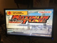
Hey there, I recently obtained the HDD and dongle for The Idolm@ster with the intention of putting it into a custom cabinet, unfortunately there seems to be very little information out there regarding the 246/256 touchscreen games and even some of that is conflicting. I have obtained some screenshots of the inside of a cabinet (sadly the source video was low resolution), so I'm hoping someone out there can help identifying what I need and how it would need to be connected up.

First of all, I know the cabinet has the following connected to it in some fashion:
Serial touchscreen
Serial card reader
Headphone port
2x cabinet lights
A control panel with test menu buttons etc.

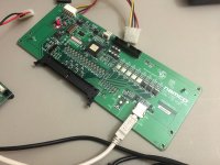
This picture is of the main PCBs, I've attached all the other pictures here: https://imgur.com/a/isBNG62

207TsCt.jpg


So, onto the problems:
1: The sound amp doesn't look like any that I can find online, a few are similar but they either don't have that lower connector or they seem to have a different one. I assume the headphone port comes off here somehow as well, but I don't understand any of this wiring. If this board isn't mandatory I'll just skip it.
2: Is the AC Switch(M2) likely for anything important, or just the exterior lights on the cabinet? The source video shows that part being repaired to fix a fault with them not working.
3: I don't really understand the wiring for getting power to... anything, does J101 on the I/O connect directly to the power supply, or does it somehow connect to the 256 first? What about the power to the amp board?

The biggest problem here is the I/O board, a few places say that it is V290, however it seems to be a variant on that as the one I bought is missing 3 D1017 transistors (R39 LED15, R37 LED14 and R35 LED13) and I don't know if that'll cause any problems. Something is plugged into the 60 pin connector (J102) but I can't work out what (the test menu buttons maybe?). There are 6 dip switches on the board but I can't find any documentation on how they should be set. J108 (the small white connector in the middle) is the one causing the most confusion however, I thought it would be the serial connector for the touchscreen (and this post by Defor seems to suggest the same), however this info that I found says otherwise:
V290 FCB PCB is almost identical to FCA PCB. The main differences are changed internal MCU code & PIC code,some extra/different connectors, less D1017 driver transistors and an added RS-232 IC.The V290 FCB PCB is used with touchscreen games such as Dragon Chronicles, Druaga Online, Idol Master etc. It supports a serial touchscreen interface, card readers and buttons.The additional devices are supported via J108 which connects to another PCB 'XOU020-A' which contains a Texas Instruments TMS32VC540x DSP, TSOP32 flash ROM and other components.
I cannot seem to find anything about this "XOU020-A" board anywhere, no pictures, no sold listings, not even any info on the Texas Instruments chip, almost as if it doesn't exist. If it is mandatory then I'm basically stuck with a paperweight as I doubt I'll ever find one.

So yeah, if anyone could offer any help or advice regarding any aspect of getting this setup it'd be very much appreciated. This is the first time I've delved into arcade hardware and it seems I unfortunately chose a real tough one.
 
@defor is our ‘in-house’ 246/256 specialist, perhaps he knows about this particular setup?
 
Yeah hopefully he will see this. I tried emailing him a few weeks ago and never got a response. He's usually quick to respond when I have a potentially undumped 246 dongle....
 
I know one of the standard answers around is "look at the mame driver" =]
https://git.redump.net/mame/plain/src/mame/drivers/namcops2.cpp

hence your discovery of: "V290 FCB PCB is almost identical to FCA PCB. The main differences are changed internal MCU code & PIC code,
some extra/different connectors, less D1017 driver transistors and an added RS-232 IC.The V290 FCB PCB is used with touchscreen games such as Dragon Chronicles, Druaga Online, Idol Master etc.It supports a serial touchscreen interface, card readers and buttons.The additional devices are supported via J108 which connects to another PCB 'XOU020-A' which contains aTexas Instruments TMS32VC540x DSP, TSOP32 flash ROM and other components."

For what ever it is worth, this dude walks through some of the differences of the various Namco boards.


I understand it Luke Morse documented the initial details of the "FCA PCB" variant.

 
Since the cabinet for The Idolm@ster shares a fair amount in common with Dragon Chronicle Online, Druaga Online and Minna de Kitaeru Zenno Training (the latter of which it seems a number of Imas cabinets were converted into) I did a bit of digging around regarding those two, and although Druaga and Dragon Chronicle were dead ends I found a couple of videos showcasing the cabinet for the brain training game (I'll just refer to it as Zenno Training for brevity going forwards) - including it being converted over to The Idolm@ster.

So, the answers I found:
1: Idolm@ster does indeed use a modified variant of the V290 I/O PCB, with 3 extra transistors, however it can run fine on the standard V290 (as used in Zenno Training and some Wangan titles).
2: The sound amp Idolm@ster uses is a variant of the IS Amp PCB 8666960501 with a bunch of extra stuff on the board, including an extra connector where there is a normally a sticker (serial number?). Since Zenno Training does not have a headphone port I have to assume all the extra stuff is to support that. The standard IS Amp PCB is compatible with Imas.
3: There is a special service menu option to disable the ALL.Net requirement and make the game function offline. Instructions how to do so are here, although it seems that having service menu buttons wired up is now mandatory.

This mystery XOU020-A PCB is still the major sticking point, along with how everything actually connects up (particularly the 60 pin connector). If only the manual for any of these touchscreen games were available online somewhere...
 
I am in the process of trying to get my Namco V290 IO to work with Wangan Midnight Maximum Tune on Chihiro... my path so far has been to hunt out the schematic. Since the game boots, my plan is to go into the test menu and try out the mappings I found in the manual at: https://www.bandainamco-am.co.uk/files/38

I've highlighted the pinout section in the jpeg attached.
MaximumTune.jpeg

Have you dug up your manual?
 

Attachments

  • DhxZMe1VAAE-Jrh.jpg
    DhxZMe1VAAE-Jrh.jpg
    160.6 KB · Views: 328
  • DhxZMgkU8AA3FlK.jpg
    DhxZMgkU8AA3FlK.jpg
    169.6 KB · Views: 394
I am in the process of trying to get my Namco V290 IO to work with Wangan Midnight Maximum Tune on Chihiro... my path so far has been to hunt out the schematic. Since the game boots, my plan is to go into the test menu and try out the mappings I found in the manual at: https://www.bandainamco-am.co.uk/files/38

I've highlighted the pinout section in the jpeg attached.
MaximumTune.jpeg

Have you dug up your manual?
I'm pretty sure that @theoddtech now has one of these IO's as well as a Chihiro. I know he was going to look into setting up an out-of-cab driving experience with real hardware. Perhaps he'll be able to chime in when he starts work on that.
 
I'm gonna try to pin it out tonight... @Symphony I don't see why you couldn't try similar.

I'm literally using the schematic as a rough guide, spot checking the pins for +5 or +12v before grounding them, and going into the JVS Test menu to see which inputs are triggered.

I printed out the diagram, and have just been writing down the results of the probing.
DhyeKdKU0AAKs56.jpg

I just picked a ground, broke out the signals I want to test with jumpers, and am now working through the Test menu.
DhyeKdIVAAAjBZf.jpg

The Analog's go to all 0000 when you find them, and the rotaries go to all FFFF. The other inputs will alter the values in SYSTEM, PLAYER 1, COIN 1 & 2.

DhyeKdKVMAAKzIY.jpg

Next I'll go into the game test menu and verify what is getting triggered.
 
You can see here in the in game test similar things occur when you find the right pins...

Note in one picture when I have it grounded out the "Gas" input is zero'd out, where as when it is NOT grounded you can see the value floating.

DhyokPhUEAApc3c.jpg
 

Attachments

  • DhyokPgUYAAIwTq.jpg
    DhyokPgUYAAIwTq.jpg
    86.3 KB · Views: 252
@Symphony posted a request to some operators who may have an Idolmaster, asking if they could provide photos or details on wiring. Specifically what is connected to the 60 pin harness, and what is connected to J108 or how the card reader is connected. Hopefully they can get a clear answer.

@Finisterre you're probably going to want and use a FCA io board (driving game), not FCB io board (touch screen game). Perhaps it will function, but they seem to each have a defined purpose according to a few resources.
 
It ain't pretty, but I've got Wangan Midnight Maximum Tune running out of the cabinet on my bench now. I'll make a proper harness soon, and make sure it is playable. All of the pins seemed to map out to the diagram I originally posted. (I had seen reports of other people finding schematics that didn't match so I wanted to double check in my case).

I would imagine you could do something very similar @Symphony, Just a little bit of time and patience, and they should pin right out for you.

Dhy0aM-UwAADN5u.jpg
 
@Finisterre you're probably going to want and use a FCA io board (driving game), not FCB io board (touch screen game). Perhaps it will function, but they seem to each have a defined purpose according to a few resources.
Indeed @brizzo. I'm primarily posting here due to the similarities...

I picked this board up off eBay listed as "Namco original arcade Wangan Midnight Maximum Tune 3 FCA2 B PCB I/O board"
https://www.ebay.com/itm/Namco-orig...e=STRK:MEBIDX:IT&_trksid=p2060353.m2749.l2649

When it arrived I had to go through some of the same stuff the original poster did in trying to identify it. The videos I posted earlier helped greatly.

As you can see in the photo from the Auction I got a V290 FCB PCB 2582960101. Of course google will throw you right at the mame driver. Here (https://github.com/mamedev/mame/blob/master/src/mame/drivers/namcops2.cpp#L614) it tells us "V290 FCB PCB is almost identical to FCA PCB" which is good for your "you should use the FCA" assertion. It specifically mentioned the games that the original posted has too "The V290 FCB PCB is used with touchscreen games such as Dragon Chronicles, Druaga Online, Idol Master etc. It supports a serial touchscreen interface, card readers and buttons". From reading this comment "The main differences are changed internal MCU code & PIC code, some extra/different connectors, less D1017 driver transistors and an added RS-232 IC" I figured they were backwards compatible, with some added features for the game @Symphony is playing.

I can't speak to the pedigree of my board, or why the seller claims it came from a Maximum Tune cart, but I've got to take his word! Seems legit so far. I'll keep you in the loop once I actually wire this up. I've got to remove my S-JIHP header and solder some things up to test. It is late though! I'm a bit spent.
 
Last edited:
I am in the process of trying to get my Namco V290 IO to work with Wangan Midnight Maximum Tune on Chihiro... my path so far has been to hunt out the schematic. Since the game boots, my plan is to go into the test menu and try out the mappings I found in the manual at: https://www.bandainamco-am.co.uk/files/38

I've highlighted the pinout section in the jpeg attached.
MaximumTune.jpeg

Have you dug up your manual?
Seems we both purchased our V290 boards from the same seller. Thanks for posting that Wangan manual, assuming that Idolmaster doesn't have a crazy different wiring setup then from what I can puzzle out the IS Amp and AC Switch both aren't going to be necessary for my setup - the former being tied to headphones and speaker output (which I'll just take my own way from the RCA cables) and the latter probably being tied to the two exterior lamps on the cabinet. Unfortunately despite trawling a lot of Japanese sites I cannot track down a manual for any of the touchscreen games.

I have to admit that I have no knowledge of electronics so these wiring diagrams are quite overwhelming (especially anything related to the power wiring), but I'm determined to finish this project off if I can get the necessary parts.

I do also have a couple of new images from inside the Zenno Training cabinet which, while not particularly useful, shows very roughly the areas of the 60 pin that are connected up (seems to be in the 1-3, 9-14 and 21-28 range?) and what buttons are connected in the service panel. They can be found here: https://imgur.com/a/C71DGEZ

@Symphony posted a request to some operators who may have an Idolmaster, asking if they could provide photos or details on wiring. Specifically what is connected to the 60 pin harness, and what is connected to J108 or how the card reader is connected. Hopefully they can get a clear answer.
Thank you very much for doing so, fingers crossed for some good news.
 
"very roughly the areas of the 60 pin that are connected up (seems to be in the 1-3, 9-14 and 21-28 range?) and what buttons are connected in the service panel"

So after probing my board out a bit, what I found was that there are 8 ADC's connected right in that pin area shown, and a few button pins that go to "Player 1". I have a feeling specific games use the various ADCs so all of the wiring will be similar (obviously not in the same order, or even using the same ADC numbers of course), on the edges is where power and ground like to live. One side also has what appear to be relay triggers for the various lights, and such.
 
Huge progress has been made today, after hours of searching I came across a video of someone attempting to significantly shrink down the footage of an Idolmaster arcade setup - this includes them replacing the CRT touchscreen monitor with an LCD screen and (I think)resistive touch panel which is hooked up to a 3M Touch Systems EXII-1020/1050/1060SC Rev 2.1 PCB (hard to work out the exact model, mostly all seem to be the same) - the strangest part is that J108 is NOT used at all for this setup, so I'm at a loss as to what it is normally used for.

So, here is the video. Unfortunately there are no detailed views of the wiring so I'm not quite sure how they have this touchscreen connected (although it looks like they're splitting it directly from the 3M PCB and sending it... somewhere?), but hopefully someone here with knowledge of the 246/256 may be able to make sense of it. There is a follow up video here but aside from another quick glance at the 3M PCB it mostly just showcases the setup running.

Edit: Ok, so after studying both videos frame by frame you can see for a split second that J108 is hooked up during the second video, but infuriatingly although you can see a split second glimpse of the corner of a potential PCB it goes to, there is nothing particularly useful. The monitor is being power independently, the 3M PCB is being powered by +12V from the orange wire and grounded from the grey wire. Red, white, black and blue go to the touch panel. The VGA board left of the screen is a Chow He CGA/EGA/YUV to VGA converter, not really sure why it is there but probably not needed. The G Sense VGA converter on the far left just seemed to be used to convert RCA to the speakers, can be ignored.

From a tiny, tiny image of the side of the original monitor I can work out that the 3M controller is an original part and I believe the touch panel he was using is as well (that small rectangular plate mounted on the visible side of the monitor is the 3M board), and I think I can make out the cables for the RS232 connection coming out of it, but cannot see where they go to.
3d9OuzW.jpg


Now, from a super blurry split second shot in 2nd video I can see the RS232 connected on the 3M board with a yellow, red and some other cables connected (I have the wiring diagrams for this board), and the J108 has a red, yellow, black and... blue? connected. From some searching around it seems that you always connect up RXD, TXD, RTS/CTS and ground and often don't use anything else, so if we assume that he used a standard molex cable with the usual colouring, the pinout for the 3M board into the J108 lines up with RXD, TXD, RTS/CTS and ground being hooked up.

Phew. This is an awful lot of guess work and conjecture, but I think there is a decent chance that J108 takes RS232 directly from the touch control board (a 3M model in this case) and this mystery XOU020-A does not exist.
 
Last edited:
Ok, so after studying both videos frame by frame you can see for a split second that J108 is hooked up during the second video, but infuriatingly although you can see a split second glimpse of the corner of a potential PCB it goes to, there is nothing particularly useful. The monitor is being powered independently, the 3M PCB is being powered by +12V from the orange wire and grounded from the grey wire. Red, white, black and blue go to the touch panel. The VGA board left of the screen is a Chow He CGA/EGA/YUV to VGA converter, not really sure why it is there but probably not needed (the 246/256 just outputs regular VGA right?). The G Sense VGA converter on the far left just seemed to be used to convert RCA to the speakers, can be ignored.

From a tiny, tiny image of the side of the original monitor I can work out that the 3M controller is an original part and I believe the touch panel he was using is as well (that small rectangular plate mounted on the visible side of the monitor is the 3M board), and I think I can make out the cables for the RS232 connection coming out of it, but cannot see where they go to.
3d9OuzW.jpg


Now, from a super blurry split second shot in 2nd video I can see the RS232 connected on the 3M board with a yellow, red and some other cables connected (I have the wiring diagrams for this board), and the J108 has a red, yellow, black and... blue? connected. From some searching around it seems that you always connect up RXD, TXD, RTS/CTS and ground and sometimes don't use anything else, so if we assume that he used a standard molex cable with the usual colouring, the pinout for the 3M board into the J108 lines up with RXD, TXD, RTS/CTS and ground being hooked up.

Phew. This is an awful lot of guess work and conjecture, but I think there is a decent chance that J108 takes RS232 directly from the touch control board (a 3M model in this case) and this mystery XOU020-A does not exist. At this point I'm going to try and get hold of a 256 unit, card reader and a touchscreen setup to start putting this into practice.
 
"I think there is a decent chance that J108 takes RS232 directly from the touch"
Do you have a logic analyzer? I would tap the outputs on the touch screen, and see what they appear to be speaking.
 
Just some progress info, after a lot of effort I'm now finally in possession of the wiring diagram for The Idolmaster station and tower assembly - and boy does it look like Spaghetti Junction. I'm going to slowly work my way through it all, work out what was originally used, what is actually necessary and draw out a more simplified wiring setup.

Something I can say off the bat though, the station and tower setup did not originally use a V290 PCB, they in fact use a V300 which I assume is what I linked pictures of in the OP - the V290 however is compatible and is used in kit versions of the station setup but I don't know if it works in a tower. Also the sound board is an ISW AMP PCB, similar to ones used in Wangan but with an extra connector to go to a HP TRANS PCB that then goes to HP JACK PCB to provide the headphone connector.
 
Last edited:
Back
Top