What's new

Frank_fjs

Multi Boyz 4 Lyfe
Legendary
Multi Boyz
Joined
Mar 3, 2018
Messages
3,410
Reaction score
5,836
Location
Australia - Adelaide
Figured I'd start this thread to show some of the various PCBs I've developed / am developing.

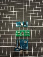
First up, from top to bottom:

Sega Master System composite video / s-video amp. Custom circuit for both. I'm rather impressed with the composite output.

PCE RGB amp. Just wanted something small and simple for easy install, all surface mount so the PCB can be mounted anywhere without risk of creating a short.

Switchless 50/60Hz kit for the Sega Master System. Custom wrote the code specifically for the MS, much better than the hacked / reworked Saturn code that's floating around.
 

Attachments

  • 38003745_10215248799426318_8759749498575519744_o.jpg
    38003745_10215248799426318_8759749498575519744_o.jpg
    245.2 KB · Views: 319
Nice n clean!
But why still the 7314 instead of 7374?
I agree, I think you should keep your design but switch to the 7316 instead. Several threads saying the 7314 isn’t “good enough”, whether true or not, it could affect sales.

Awesome work regardless, keep up the pace!
 
Just using up old stock of 7314s. Honestly there's practically no difference between the two, people really make too much fuss over it.
 
Just using up old stock of 7314s. Honestly there's practically no difference between the two, people really make too much fuss over it.
Understood, I haven't had a chance to compare, but JNX is doing a SGX mod with the 16 for me so I'll put my eyes on it through an OSSC and post if it's different, BUT there are threads about it out there and if you are wanting to sell these, I'd say just go with the 16 to shut up potential buyers...

If this is just for yourself or a small group, WTF (who!) cares, do what you do man!
 
Well actually, there is a difference. For me the main thing is that the 7314 has a LPF which cannot be disabled, for the 7374 you CAN disable it. This gives you a slightly sharper image, and also, as I have the OSSC in my chain which has the LPF already on, it doesn't do much good. The drawback is that the chip of the 7374 smaller, making it harder to solder to.

Anyways, here's a discussion where some of the talented guys (like retrorgb and borit) shed some light on this topic as there are more differences between the two:

https://shmups.system11.org/viewtopic.php?t=58863
 
I use CRT so for me it makes little difference. I suppose using external devices such as the OSSC and LED there is a benefit but I'm not a fan of gaming that way.

I do have 7374s but for this MOD prefer the 7316. If I were to use clean sync I'd utilise the 7374 for the extra channel but with PCE I like to retain the original composite output and therefore use it as sync.

Not looking at selling the PCE kits, they're just for me. Have sold a heap of the switchless kits though.
 
Thanks for clarifying @Frank_fjs!
For CRT gaming it wouldn’t make a difference indeed, but with an OSSC you don’t want 2 LPF’s in your chain, or even 3 if you use the previous revision of the gscartsw :)
 
I really, really don't like retro gaming on modern displays! Even with devices such as the OSSC it's just not right. I understand CRTs aren't practical and are getting harder to find, so I have myself set with a stash of them.
 
Same here buddy ;)
Using a XM29 as main display, and hoarded some PVMs and BVMs over the last few years :D

Too bad they are such a hype nowadays and it is just impossible to find a D32...

Regarding the 7314, that would potentially be a deal breaker if you would sell the boards at some point, hence why I wondered why you used it
 
How is the gscart applying a LPF? What ICs are in there?
 
I did intend on using 7316, this is actually printed on the silkscreen beneath where the chip is soldered, just threw a 7314 on as I have heaps of them on hand and for my own personal use it doesn't bother me. There shouldn't be any issues using a 7316 as the LPF is effectively disabled.

I may design a PCB with the 7374, a switch to enable / disable the LPF, the option of utilising csync and more thorough attenuation but for now I'm happy with a rather compact, low cost, simple and effective solution.
 
I have noticed that some adapters have very short edge contacts and key notch. This makes the whole adapter "wobbly" when you insert it in the JAMMA connector on an EGRET II.

Did some checking and most contacts on JAMMA edge connectors are normally 10mm long with the key cutout slightly longer.

Check your CAVE PGM PCBs :)
 
Last edited:
I have 9mm on the finger, inserts into all my jamma edge connectors with about 1mm spare.
 
It probably looks like less in the picture due to the solder mask cutout.
 
Back
Top