What's new
Hmm, so just throw the cSync input into a LM1881? Any changes necessary to the typically usages in the docmentation?

[PDF]
LM1881 Video Sync Separator - Texas Instruments
https://www.ti.com/lit/ds/symlink/lm1881.pdf

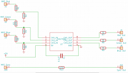
For my mini9 board, I just added pots and a spot for a 470ohm on the sync line as a bare minimum if someone wanted to get something working off the output from the JAMMA edge, should I remove the 75ohm on the RGB boards output and use something like 100ohm trimmers on the breakout board to allow individual adjustments to the lines if desired:

received_1180888425622508.png
 
Fwiw, this is what I've been working on:

http://imgur.com/a/Lkpmu2n

The jamma edge breakout was built specifically for the case I designed, doesn't modify the signal at all. Output board is as displayed in the last pic with pots to attenuate the RGB lines, and a resistor to bring the TTL sync to consumer levels at the minimum, with bypass jumpers if you want to skip soldering in the components.

Just gotta dial in the RGB circuit, and the enclosure is pretty dang close to a drop-in consolizer.
 
The 75R are voltage dividers so I wouldn't be removing them. I think the pots would need to be installed prior to the output stage?
 
I guess he wants to make the resistors "skippable" just in case somebody wants to use a RGB cable with the resistors already installed. I've placed the resistors etc. directly on the pcb because it should be better to have no components in the cable (see here why: https://shmups.system11.org/viewtopic.php?f=6&t=52249&start=108).
totally agree with that thread, one way I fought that in my previous builds was to have a female SCART port in lieu of a mini-9, as it would only work with a male->male setup, perfect for an OSSC or Framemeister.

However, with all the Genesis 2 related options, I wanted to aim for that av-out to give people using this enclosure as many options as possible (Gen2 SCART cable, hd RetroVision, Rad2X, etc)
 
  • Like
Reactions: SVM
I still couldn't get it to sync properly on my TV but it works great on PVM and through OSSC or a component converter
Personally I like the Jassifier device @Frank_fjs designed for us, it outputs 8pin mini at SCART levels.
9pin mini sucks because ya, best way to use it is Genesis SCART cable and that has components in the cable.

Components in cables is WRONG! :cursing:
 
Having read through this thread and seen some different views on resistor configurations can anyone confirm that the original resistor values output correct signals for a MVS connected through RGB Scart - Retrotink 2 x - Flat panel TV.. I am in PAL land. I am about to order the components for @SVM cMVS board :)
 
It comes down to your screen and preference. I found it way too dark on my TV, but it was fine on the PVM. The resistors I changed ended up working well on both.

Build it as originally specified and then make the changes as required.
 
  • Thank you that's a neat little board. Yes please that would be most helpful. do you have the BOM as well?
Until I get the parts I'm using a much simpler circuit as attached.
 

Attachments

  • rGPdzAw.png
    rGPdzAw.png
    99.3 KB · Views: 281
Hey folks, anyone know why my screen is cut off from the right side? I presume it's some sort of sync resistance value. I'm using Neo-Geo MVS RGB 1.0.
 

Attachments

  • 16188540725566305565836015291163.jpg
    16188540725566305565836015291163.jpg
    177.9 KB · Views: 214
  • 16188540893041194570103189697727.jpg
    16188540893041194570103189697727.jpg
    127.2 KB · Views: 312
This is the typical RGB shift. I you can't adjust the image via the TV menu you'll need a RGB Shifter or similar.
 
This is the typical RGB shift. I you can't adjust the image via the TV menu you'll need a RGB Shifter or similar.
RGB shifter? It's cool I have a retro tink scart X. I do want to sell off the CMVS at some point though and I know someone on eBay will complain. Funny thing is, on this TV all I get is a blank image on the tink and Neogeo. On my 4k TV and my 1080i plasma TV it shows perfect with the Tink. Very odd.
 
Here you can read about it: https://playoffline.wordpress.com/cable/rgbshifter/ It's in German but the Google translator will help you out. ;)

And here you can order a pcb: https://oshpark.com/shared_projects/3q6Lg1ya ...

or you order a complete unit from http://arcadeforge.net/Pi2Jamma-Pi2SCART/CRT-RGB-Pic-Shifter::306.html

But I'm sure you can correct the picture position in your TV menu, too...
Thank you for the information and the links. Was quite an interesting read. I've tried all the settings on that particular TV set and it doesn't want to play ball! On my plasma I get no such image shift. I guess it all depends on the television.
 
i don't remember if i had already asked, do anyone sell this pcb pre assembled?
 
I have a couple pre assembled as long as you are ok with shipping from Australia
 
Hello everyone. I have read the thread several times. But I still don't understand what is the difference between Philenotfound's design and noob's design. I've been going through the component list for the first design and the values for resistors R9 through R12 are missing. What should be the value for those resistors? I'm thinking of connecting a Neo Geo MVS MV-1C with Retrotink 2x SCART to a Full HD LCD TV and I don't know what the best design would be.
 
Last edited:
In the meantime @pacoarcade has presented his Picogun. Maybe the pcb is a better alternative because the signals seem to be attenuated + you have the possibilty to adjust the RGB channels via pots additionally.

https://www.arcade-projects.com/threads/picogun-video-buffer.13775/

But I don't know were to order the pcb...

Here is version 3.2. https://www.pcbway.com/project/ShareProjectPublish?id=6734

But the latest version seems to be 3.2.6
Thanks for the info. I didn't know there was another design in development. On that PCBWay link, can I buy it? When I try to accept the order, it throws me an error. I also don't see the .gerber files. On the other hand, does this design give better results than Philenotfound and noob?
 
Hi, if you want a Picogun feel free to contact me via PM. I can assemble some of them for 20€ each or 50€ x3 plus shipping to Europe (payment via SEPA transfer). I can also sell bare PCBs for a cheaper price if you prefer to assemble them yourself.

Gerbers are no longer available, only the schematic. Making PCBs is expensive (testing, components, etc), so I want to sell them to get back at least a part of the already spent money and get funds to continue with my developments.
 
Back
Top