You are using an out of date browser. It may not display this or other websites correctly.
You should upgrade or use an alternative browser.
You should upgrade or use an alternative browser.
- Thread starter xodaraP
- Start date
Well I’m stuck. Switched the CLOCK and DATA wires back but still a white screen. My multimeter probes are pretty sharp, but testing connectivity with individual FPGA pins is beyond my skill level. At this point I just want to pay to ship the whole thing to someone for repair...
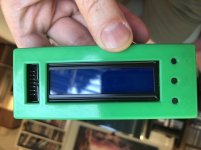
By the way, my recently purchased LCD display from HighScoreSaves doesn’t fit in the CPS2 multi housing from Bit District! Does anyone know if this is a temporary issue or if the LCDs have changed permanently? Thanks again!

By the way, my recently purchased LCD display from HighScoreSaves doesn’t fit in the CPS2 multi housing from Bit District! Does anyone know if this is a temporary issue or if the LCDs have changed permanently? Thanks again!

Last edited:
xodaraP
Legendary
You're in the US so @Mitsurugi-w is your man to repair it.
Given you've lost pads I'd suggest that your connections aren't there and you will need them jumpered.
Given you've lost pads I'd suggest that your connections aren't there and you will need them jumpered.
I have finally gotten around to putting my multi inside a CPS2 case.
However I am getting jailbars on the graphics when I mount it in the CPS2 case.
The reason for this is removal of the support bar from the case to fit the multi PCB.
Anyone have an idea how I can solve this in the simplest manner ?
Symptom

Post removal

This point does not get enough pressure.

However I am getting jailbars on the graphics when I mount it in the CPS2 case.
The reason for this is removal of the support bar from the case to fit the multi PCB.
Anyone have an idea how I can solve this in the simplest manner ?
Symptom
Post removal
This point does not get enough pressure.
Last edited:
so do the jailbars happen if you seat the kit without a plastic case? I would recommend just reseating the entire multi board and then reseating the entire B board onto the A board. The jailbars are typical of a bad connection between A and B boards. also, is it every game and exactly the same? if so you know that it's not a ROM/Multi issue.I have finally gotten around to putting my multi inside a CPS2 case.
However I am getting jailbars on the graphics when I mount it in the CPS2 case.
The reason for this is removal of the support bar from the case to fit the multi PCB.
Anyone have an idea how I can solve this in the simplest manner ?
All is good if I press down hard on the PCB when the lid is not present.
The moment I but everything inside the case the PCB will flex since the support bracket has been removed.
I need a simple way to reintroduce the support bracket.
The moment I but everything inside the case the PCB will flex since the support bracket has been removed.
I need a simple way to reintroduce the support bracket.
Before this cart became a multi it was working 100%.
How to reproduce:
. Assemble the cart but leave out the screws
. Mount the cart on the A board
. I get jailbars
. I pop of the top lid
. I can see that the section which does not have the support anymore is not inserted fully
. I press down with my thumb
. All is good
So I need a way to reintroduce the support bar which has been removed again.
xodaraP
Legendary
I had a similar issue with one I installed, the joints on the IDC connectors are old and not making the best contact. Some of the pins may be dirty too.
I solved it by reseating the board a couple of times and found that holding it down worked, but so did pulling it out slightly. It was still firmly held in but not shoved down as far as it would go.
I solved it by reseating the board a couple of times and found that holding it down worked, but so did pulling it out slightly. It was still firmly held in but not shoved down as far as it would go.
Some pcbs will give you fits because the support is gone. I've used hard foam to stcack inside to add support. Whatever you use has to be rigid and not give way when pressed.
Good solution, what do you define as "hard foam" ?Some pcbs will give you fits because the support is gone. I've used hard foam to stcack inside to add support. Whatever you use has to be rigid and not give way when pressed.


