You are using an out of date browser. It may not display this or other websites correctly.
You should upgrade or use an alternative browser.
You should upgrade or use an alternative browser.
- Thread starter xodaraP
- Start date
Update: You guys were all correct! However it was the pin and darksoft board connection C32 pin that was bent.


for future reference, check pins above the board as well.
Thank you again to everyone that has helped. If I had a choice, I would use a -7 board; less headache and issues.
for future reference, check pins above the board as well.
Thank you again to everyone that has helped. If I had a choice, I would use a -7 board; less headache and issues.

I also managed to install mine and got it working first try! It worked both in my Dynamo cabinet and with the CPS2HDMI AV Interface on my LCD screen. Luckily a gentlemanly scholar named @acblunden2 sold me a infinikey a year or so ago to restore my board when I joined these forums and also included a JST connector with wires pre-crimped. I had no idea what this connector was for until last night when installing and realized my revision 7 board with Gpal would require it to enable key writing. I find it surprising it wasn't included in the kit. Since the drop down menus were not working when I ordered my kit I am not sure if it is an option to purchase separately.
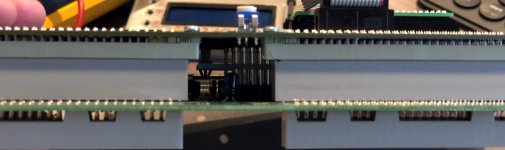
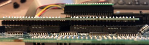
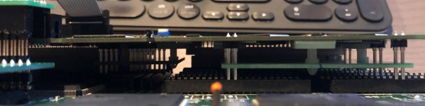
The only part that was troublesome for me was connecting the smallest connector piece between the two PCB's. For me the smaller PCB sat lower a bit and was starting to bend pins. I had to raise up the smaller PCB to half inserted so it would be flush with the large PCB, then sit the connector on then and push it all down at the same time.
I also accidentally cut off the wrong plastic peg Maybe consider gluing it back.
Now I just need to make it look pretty. Gonna order the screen 3D printed enclosure, longer cable, and paint the shell something real purdy.
The only part that was troublesome for me was connecting the smallest connector piece between the two PCB's. For me the smaller PCB sat lower a bit and was starting to bend pins. I had to raise up the smaller PCB to half inserted so it would be flush with the large PCB, then sit the connector on then and push it all down at the same time.
I also accidentally cut off the wrong plastic peg
Maybe consider gluing it back.Now I just need to make it look pretty. Gonna order the screen 3D printed enclosure, longer cable, and paint the shell something real purdy.
I had similar issues with the bridge being really hard to mount compared to a ribbon cable. I've had to take my kit apart quite a bit due to issues with connections (still not working) and I've bent those pins a few times trying to get them to line up properly under a lot of force.The only part that was troublesome for me was connecting the smallest connector piece between the two PCB's. For me the smaller PCB sat lower a bit and was starting to bend pins. I had to raise up the smaller PCB to half inserted so it would be flush with the large PCB, then sit the connector on then and push it all down at the same time.
maiden2099
Student
Hey Guys,
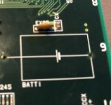
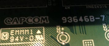
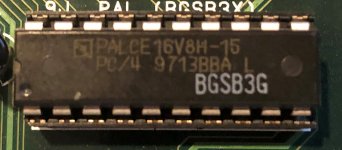
Just got my CPS2 Multi, and installed and I'm stuck on a black screen. Boots up green, load a game, goes to black then nothing. I started with working A and B boards and I removed the battery and all of the socketed chips. The B board is a MSH vs SF revision 7 and had a PAL G installed on it.
Regards,
Anthony
Just got my CPS2 Multi, and installed and I'm stuck on a black screen. Boots up green, load a game, goes to black then nothing. I started with working A and B boards and I removed the battery and all of the socketed chips. The B board is a MSH vs SF revision 7 and had a PAL G installed on it.
- Discharged EXC5 as well as CCI.
- Installed key writing wires and used the encrypted rom set from arcade projects roll up pack.
- Checked multiple times that key writing wires installed correctly.
- Removed the key writing wires (pads look good and intact), tried decrypted rom set.
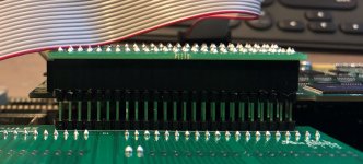
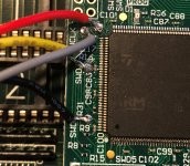
- Checked all pins on kit, none bent, all making solid contact with board below.
- Checked multiple times to make sure interconnect board installed correctly. (RU symbol toward the left or JAMMA connection).
- Removed and reseated the kit several times.
- Tried 3 different SD cards formatted FAT32 and copying all files in one action using Windows 10 machine.
- Re-installed firmware on kit.
Regards,
Anthony
Attachments
-
 battery.jpg821.5 KB · Views: 131
 -
 BoardConnectors.jpg740 KB · Views: 130
 -
 boardversion.jpg576.6 KB · Views: 165
 -
 interConnect.jpg731.2 KB · Views: 128
 -
 mainBoard.jpg892.6 KB · Views: 135
 -
 Pal.jpg352.6 KB · Views: 130
 -
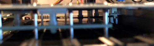
 sideConnections.jpg739.6 KB · Views: 150
 -
 Wiring1.jpg802.3 KB · Views: 160
 -
 BoardConnectors1.jpg755.8 KB · Views: 156
 -
 wiring2.jpg799.9 KB · Views: 128
Hi Anthony,
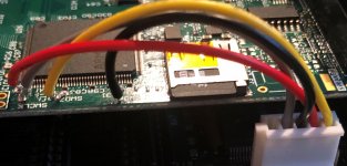
those wires don't look very neat in my opinion. There may be some undesired solder contact there.
First of all, please unplug the 4 wires that go to the b Board and try loading a game that works without battery. There are many of them. Just to be sure, the KEY file in the directory of the game must be full of 0xFFFFFFF
If that doesnt work, then make sure that the join between both boards of the kit is properly sitting and in the right direction. Test with a meter.
If none of this works, I'd suggest that you sent to @Mitsurugi-w so he can have a look.
maiden2099
Student
Hey @DarksoftHi Anthony,
those wires don't look very neat in my opinion. There may be some undesired solder contact there.
First of all, please unplug the 4 wires that go to the b Board and try loading a game that works without battery. There are many of them. Just to be sure, the KEY file in the directory of the game must be full of 0xFFFFFFF
If that doesnt work, then make sure that the join between both boards of the kit is properly sitting and in the right direction. Test with a meter.
If none of this works, I'd suggest that you sent to @Mitsurugi-w so he can have a look.
The wires were worse the first time, didn't have any solid wire, only stranded. Tried to come down onto the pads as to not hit any of the resisters surrounding the pads.
If I just unplug from C9 is that enough to test decrypted roms or do I need to remove the wires as well?
As for the key file with all 0XFFFFFF, I'm assuming that's the same as the NoBattery.key on the site.
I ran the test roms 10101010 and 01010101 and its seemed to work fine. Not sure what I am to expect with what's displayed on the monitor but the LCD said its all good. Sometimes the monitor is all black sometimes it goes to green.
Also, where should I put the probes from my multimeter to check connections between the boards? Am I just looking for continuity.
Sorry for all the NOOB questions but I'm a bit new at all this. Just finished navigating and getting through a Naomi CF setup/memory card compatibility etc the last month. I thought this was going to be a cakewalk compared to what I was dealing with on that. lol
That should be enough, if still doesnt work, then remove the cables, they may be doing a short. Also inspect for solder blobs that may have follen during the installation process.If I just unplug from C9 is that enough to test decrypted roms or do I need to remove the wires as well?
Yes, but has to be named "key" and be 20 bytes in size.As for the key file with all 0XFFFFFF, I'm assuming that's the same as the NoBattery.key on the site.
Exactly that.Also, where should I put the probes from my multimeter to check connections between the boards? Am I just looking for continuity.
No worries. We've all been learners.Sorry for all the NOOB questions but I'm a bit new at all this.
maiden2099
Student
@Darksoft
We have success!
Troubleshooting Steps:
Thank you to everyone for all your contributions to this thread, if not for all your work I would have thrown all this shit at a brick wall 2 days ago. Hopefully my experience will help some of you that are still having trouble.
Now I finally get to stop and actually play the damn thing... Until my 30 CF cards for my Naomi come tomorrow and I spend the better part of 2 days extracting security sectors, flashing cards and testing them all.
We have success!
Troubleshooting Steps:
- Tested continuity across the board with a Multimeter
- Every Pin was connecting between the Multi and my B-Board properly.
- Unplugged the C9 cable, tested with decrypted ROMs and ensured the key files were correct
- Green Screen
- Removed the key wiring and retested with decrypted ROMs
- Green Screen
- Tested on another good A board
- Green Screen
- Put all the original ROMs back on, installed an Infinikey
- When I first booted it I saw a few garbled sprites but then to a green screen
- In frustration I put pressure on the interconnects between the A & B board while turning it on
- Successful Boot
- So then I put on the retention clips
- Successful Boot
- Removed my original ROMs again, removed the Infinikey, reinstalled the Multi with a decrypted rom set (put on the retention clips)
- Successful Boot but upon switching games It wouldn't reset automatically. I needed to shut it down manually and reboot to change games.
- Then I put it back on the bench, soldered the key writing wires, changed the ROMs on my SD
- Successful Boot and changes games seamlessly.
- Removed the required post on B Board cover, reinstalled cover
- Successful Boot but garbled audio
- Removed the black clip on top of the LCD Connector, reinstalled cover
- Successful Booting constantly
Thank you to everyone for all your contributions to this thread, if not for all your work I would have thrown all this shit at a brick wall 2 days ago. Hopefully my experience will help some of you that are still having trouble.
Now I finally get to stop and actually play the damn thing... Until my 30 CF cards for my Naomi come tomorrow and I spend the better part of 2 days extracting security sectors, flashing cards and testing them all.
Congratulations! I'm glad that you got it done!Thank you to everyone for all your contributions to this thread, if not for all your work I would have thrown all this shit at a brick wall 2 days ago. Hopefully my experience will help some of you that are still having trouble.
Hello people wiser than me ;
I installed a multi kit into a v4 CPS2 board last night with zero problems.
Today I install a second multikit into my own v4 CPS2 board and have experienced some problems.
Naturally I have checked the usual - all pins have good contact (by eye), CN5 has been shorted, 4 key writing lines have good contact at both ends (used flux and cleaned up afterwards with electronics solvent), tried various known working SD cards (sandisk ultra and Kingston), PAL-G supplied by saveyourgames.it.
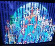
So I get a pink or red or coloured screen. The LCD shows writing key, then lists the games. I try and load a game, it only shows me one star "*" then writes the key. The game is not properly writing to the memory on the multi.
The very first boot of the multi, I used a known good SD (used last night on the working install) and it said SD card missing. I only have one light on the multi, the power light, no second light.
Each time I try and load a game, it only shows one star "*" then programs key, then boots to coloured screen.
Same with decrypted set. This will be my 5th CPS2 multi install, so I am not brand new to this.
Any advice would be appreciated")
edit: the LCD has also reported an error after trying to load a game.
edit: @xodaraP thanks but no bridge, very decent solders. the second LED not being lit i think is an indication of something much worse
edit: The second LED, next to the FPGA, flashes very fast once when the unit is powered, but stays off.
edit: always now when powered up it just says init lcd and nothing else. trying 3 diff SD which work fine on other multi kit.
I installed a multi kit into a v4 CPS2 board last night with zero problems.
Today I install a second multikit into my own v4 CPS2 board and have experienced some problems.
Naturally I have checked the usual - all pins have good contact (by eye), CN5 has been shorted, 4 key writing lines have good contact at both ends (used flux and cleaned up afterwards with electronics solvent), tried various known working SD cards (sandisk ultra and Kingston), PAL-G supplied by saveyourgames.it.
So I get a pink or red or coloured screen. The LCD shows writing key, then lists the games. I try and load a game, it only shows me one star "*" then writes the key. The game is not properly writing to the memory on the multi.
The very first boot of the multi, I used a known good SD (used last night on the working install) and it said SD card missing. I only have one light on the multi, the power light, no second light.
Each time I try and load a game, it only shows one star "*" then programs key, then boots to coloured screen.
Same with decrypted set. This will be my 5th CPS2 multi install, so I am not brand new to this.
Any advice would be appreciated
edit: the LCD has also reported an error after trying to load a game.
edit: @xodaraP thanks but no bridge, very decent solders. the second LED not being lit i think is an indication of something much worse
edit: The second LED, next to the FPGA, flashes very fast once when the unit is powered, but stays off.
edit: always now when powered up it just says init lcd and nothing else. trying 3 diff SD which work fine on other multi kit.
Last edited:
@Darksoft thanks - the firmware update worked (copied the flash.img to root of SD card and booted up), LCD displayed showed all solid blocks along the top row of the LCD screen. then went to select game screen. The second light was on at this point. I tried to load a game to memory, it hung after one * .
After rebooting the cps2, exactly the same as before, no second LED, games only show one "*" when loading, then tries to write key then red screen.
I have re-seated the entire kit as well, no busted legs or anything, all looks good. Same as before. Open to more suggestions
edit: @xodaraP same with both enc and deenc roms, they load one * of the game, then it says HaveFun! (as if its finished and worked) then nothing but coloured screen. Using same rollup kit or avalaunch Kit which is working perfectly on the other multi kit I installed yesterday.
Last edited:
