goguelnikov
Beginner
I think, but I’ll check. Each chip has its small dot in front of the triangle on the PCB.are you sure that you used N type and R type where it corresponds?
Maybe some of the chips are damaged or fake...
I think, but I’ll check. Each chip has its small dot in front of the triangle on the PCB.are you sure that you used N type and R type where it corresponds?
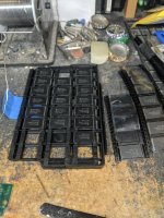
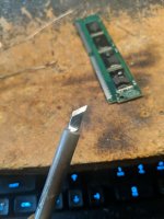
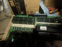
Anyone knows the vaule of the small bypass caps?Now we are finished with the reverse pinout ICs. Next, we'll start soldering the normal pinout ones. One thing is important placing the flash ICs correctly. You'll notice that there are triangle marks on the PCB. These triangle marks indicate the #1 leg of the IC should be located there. The flash ICs have a tiny circle on them (they also do have a larger circle but that is something else) indicating the #1 pin.
I put circle on the photo to help explain what I mean...

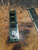
With the same soldering technique I solder the normal pinout flash ICs one by one...

And the other side...

Top view... All in place, we are finished

Don't forget to clean the flux with IPA and/or Acetone and double and triple check the legs with magnifying glass one more time. Sometimes your iron tip may accidentally touch the neighbor IC leaving a solder bridge that you may have not noticed...
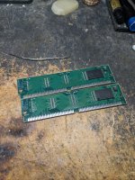
Anyway, after cleaning and examining twice, this is what we end up; One empty PCB one 128Mbit SIMM

And the ultimate question! Will it work?


Are those Fujitsu 90PTFR and 90PTFN chips? where did you source them? I've tried several suppliers and either get PTFN when it should be PTFR or I get slower speed (120) chips.Thanks for this thread @yavuzg .
")

