What's new
Here is the connector. Anyone know what part mates with it? Looks quite different from the part linked above. Maybe I’m better off chopping this to a connector for the Naomi and for an atx supply.
 

Attachments

  • 385566E8-90F5-462A-B70B-41D222CAD0EA.jpeg
    385566E8-90F5-462A-B70B-41D222CAD0EA.jpeg
    158.7 KB · Views: 108
Thats a TE Connectivity Amp UP (Universal Power) connector. Very common on Sega and other Japanese arcade machines.

Don't cut it off; buy the appropriate mating connector.
 
Ok, help me find it? I don’t know how you guy find any of this stuff. Edit, just saw link above, thanks.
 
I don't recall that being on my reader... maybe it is. I'm not home, so can't confirm at the moment. Can you provide photos of the unit and entire wiring up to that?
 
Yep. I also noticed a few places with no harness attached, so I’m wondering if any of those are needed. I’ll post more photos tonight. I also have another reader coming so will be curious to see if it matches this one or is different. Hopefully it is a match so I can test with the same harness.
 
Yep. I also noticed a few places with no harness attached, so I’m wondering if any of those are needed. I’ll post more photos tonight. I also have another reader coming so will be curious to see if it matches this one or is different. Hopefully it is a match so I can test with the same harness.
I checked my ID3 reader and it all has pretty short wires coming from connectors plugged into various parts of the reader itself, terminating in a single 15-position connector that has 5v, 12v, ground, and serial communication wires. I think a reader should come with that as a minimum requirement because otherwise you're likley going to have to figure out pinouts and connectors that probably aren't documented anywhere. You may have ended up with some downstream connectors/harnesses (hopefully in addition to the one I'm referring to). That one you shared I think is just power and would plug into the main wiring harness close to the PSU.

I believe this is the mating housing to the 15-position connector that's on my unit (it appears to be an end of life product - note the notches on the edges because I believe there are similar housing that don't have them and won't mate up properly):
https://www.digikey.com/products/en?keywords=03-06-1152

Edit: I checked the wiring diagram and am not sure what to make of the inner connector documented there. It appears to be a 12-pin one:
ID3 reader pinout.PNG

For the record: I don't have a stock ID3 setup, am and not sure what is considered stock wiring on the reader units. I'm also not sure if there are variations. I simply ordered what was supposed to be an ID3 reader and figured out the wiring with the diagrams and testing.
 
Last edited:
ok, maybe the 12 pin is what I have here. I’ll take more pictures when I get some time. Thanks for all the help! I want to get this thing hooked up eventually.
 
Alrighty. Here is the reader I have, bought as “working”. I have two and they are the same. Both have just this 12 pin harness.
 

Attachments

  • ACF41023-BEE1-4146-A9DA-FD709C009070.jpeg
    ACF41023-BEE1-4146-A9DA-FD709C009070.jpeg
    364.9 KB · Views: 110
  • 51288DB1-C818-4AC6-91C3-13215A0D5BC7.jpeg
    51288DB1-C818-4AC6-91C3-13215A0D5BC7.jpeg
    283.9 KB · Views: 109
  • B3B1D3AE-BC41-4549-84BF-BE18A90D0132.jpeg
    B3B1D3AE-BC41-4549-84BF-BE18A90D0132.jpeg
    351.5 KB · Views: 108
  • D25E527B-68D1-4717-8B97-C320A82ADDE2.jpeg
    D25E527B-68D1-4717-8B97-C320A82ADDE2.jpeg
    313.7 KB · Views: 109
Alrighty. Here is the reader I have, bought as “working”. I have two and they are the same. Both have just this 12 pin harness.
It looks like the same kind of harness that's on mine, so you're probably good to go once you create a mating adapter. I double checked and mine is a 15 pin and a different series connector.

It might be worth sharing the details of the included rom chip. I think I photographed and shared mine much earlier in the thread.
 
Got some time to look at this more. It looks like the connector on my units is just upside down compared to the one in initial d3. I’m looking at the schematic in the id3 manual here. Got my connectors and pins. Now I just need to wire it up. I don’t have a steering wheel yet though, I hope to get that going soon.
 

Attachments

  • 936F6D12-23F4-4259-B466-F8630D4206FA.jpeg
    936F6D12-23F4-4259-B466-F8630D4206FA.jpeg
    727.7 KB · Views: 104
Got some time to look at this more. It looks like the connector on my units is just upside down compared to the one in initial d3. I’m looking at the schematic in the id3 manual here. Got my connectors and pins. Now I just need to wire it up. I don’t have a steering wheel yet though, I hope to get that going soon.
I think you're good to go. Notice the numbering on the 8-pin connector. It just has the pins numbered the opposite way as the other connectors near it. It's still correct and should match up pin for pin to the wiring diagram you printed. You've just got some different wire colors you'll need to keep track of.

The other good news is that you've got the same firmware that's on my unit, so I think you won't have any problems running it on ID3.
 
I'm so happy you guys were able to play your driving games properly, but so sad that Virtua Fighter 4 could not be helped in such a way. I remember how the cards would be used even for moves that had to be chosen as well. I know the cards had a backup copy of the other data as well (names, records, outfits, and items.)

Anyhow, good job on this. I can hope that something will come up one day.
 
Last edited:
I think I'm finished with the ID4-5 card emulator script. I have not had any failures on ID4 and 5 with the testing I have done.

If anyone wants to test, let me know.

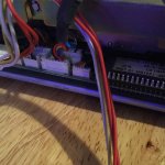
You would need a serial adapter to go from the port on the Lindbergh to the port on the PC running the script (i.e. I use a TU-S9 USB adapter on my laptop). I haven't tested to tell if RTS/CTS are needed, but the physical card reader has them and I incorporated them into my adapter.

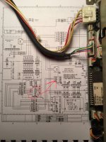
Basically you need an adapter that does this:
PC to Lindbergh
GND (pin5) - GND (pin5)
RX (pin2) -TX (pin3)
TX (pin3) -RX (pin2)
RTS (pin7) -CTS
CTS (pin8) -RTS (pin7)

You can buy a ready-made cable to do this, but make sure it is NOT a straight-through cable. You need a female to female null modem cable that crosses the wires over from one to the other as needed.
Late late response but literally just got my Mutliboot courtesy of Darksoft, can we use the same cable used for the script for the Naomi? i'm not sure where this connects to the Lindbergh and what kind of cable you suggest if the old 1 can't be used, any information would be appreciated.
 
I know most people don't care, but this does not do all of the Naomi 1/2 cards. It just the ones meant for driving games.

I'll go back to my corner now.
 
Back
Top