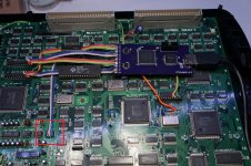
Yes it supports audio. The audio is generated from the IC I have highlighted in my install. Try testing the audio in the configuration menu.Finally!, thanks to @jassin000 for helping me out! As alwaysVideo looks amazing.

Question though: does this mod not support audio from the HDMI? Only way i got audio was from the RCA cable. I don’t think we missed any steps.
You are using an out of date browser. It may not display this or other websites correctly.
You should upgrade or use an alternative browser.
You should upgrade or use an alternative browser.
- Thread starter RGB
- Start date
J
jassin000
We did, his was silent as could be.testing the audio in the configuration menu
And I soldered thos 4 feet you outlined in red above (maybe the order is wrong? your PCB is different looking so I can't really compare).
Have you tried the 'powering it up with the volume down depressed trick'? I don't think this will work though as you say you are getting audio through the RCAs. Although my board is different, the IC is the same.

J
jassin000
It won't work for you because you have audio... just via RCA jacks only.trick and nothing
The "trick" is that it restores audio IF your audio isn't working at the CPS2 A-board level (sometimes after writing a game on DS multi).
Again that's not what's wrong with yours...
I don't think its hooked up correctly, and so far no one can give me a clear indication of what go's where (just low rez images or different revision PCBs).
I said I would help out with this, and really the mod does look fantastic... But man, this takes the cake for worst install directions ever.
Wouldn't recommend to anyone in its current state.

I don’t believe we did sir. I will checkit's hard to tell from the pics, but did you bridge jumpers J3, J5 and J6 on the AV board (step 3 in the instructions)?
Very tiny. If you trace your finger from the intel chip on the AV board, Start at the "I" and go left, you will see them. Took me forever to find them, almost illegible.I don’t believe we did sir. I will checkit's hard to tell from the pics, but did you bridge jumpers J3, J5 and J6 on the AV board (step 3 in the instructions)?
Also, A lot of people seem to be doing RGB's method of installing the coax cable. I followed the original instructions and went to the underside of the board. Probably doesn't matter but it may be worth a shot.
Make sure C1 and C2 are bridged.
thanks man ill look into this bridging j3, j5 , j6, which all 3 are supposed to be bridge together right? Anyone got a picture of that when they where doing their installation?Very tiny. If you trace your finger from the intel chip on the AV board, Start at the "I" and go left, you will see them. Took me forever to find them, almost illegible.I don’t believe we did sir. I will checkit's hard to tell from the pics, but did you bridge jumpers J3, J5 and J6 on the AV board (step 3 in the instructions)?
Also, A lot of people seem to be doing RGB's method of installing the coax cable. I followed the original instructions and went to the underside of the board. Probably doesn't matter but it may be worth a shot.
Make sure C1 and C2 are bridged.
It might be a good idea to post pics from your installation, because the official installation guide pictures aren't clear regarding the coax.Also, A lot of people seem to be doing RGB's method of installing the coax cable. I followed the original instructions and went to the underside of the board. Probably doesn't matter but it may be worth a shot.
AlxUnderBase
Enlightened
Yes sir ... i posted some pictures, there are full instalation. check this pbs.twimg.com/media/EEohcnDWwA…format=jpg&name=4096x4096 (look on the middle on that 3 solder joints - where is U11) . here you can check if it's the same as yoursthanks man ill look into this bridging j3, j5 , j6, which all 3 are supposed to be bridge together right? Anyone got a picture of that when they where doing their installation?
I seeee, we definitely did not touch U11, so its as simple as adding some solder to those 3 abd done? They dont look bridge to me on that picture, or do they automatically become “bridge” once you add soldering to all 3 of them individually?Yes sir ... i posted some pictures, there are full instalation. check this pbs.twimg.com/media/EEohcnDWwA…format=jpg&name=4096x4096 (look on the middle on that 3 solder joints - where is U11) . here you can check if it's the same as yoursthanks man ill look into this bridging j3, j5 , j6, which all 3 are supposed to be bridge together right? Anyone got a picture of that when they where doing their installation?
AlxUnderBase
Enlightened
3 pads on the middle of U11 ... that 6 pads must have solder on them (bridge those) and the result will be that 3 jumpers soldered (3 joints)I seeee, we definitely did not touch U11, so its as simple as adding some solder to those 3 abd done? They dont look bridge to me on that picture, or do they automatically become “bridge” once you add soldering to all 3 of them individually?
look on this picture to see how looks unsoldered
You areee the besttttt man thanks for having patience with my noob ass lol ill try this tonight and see was up.3 pads on the middle of U11 ... that 6 pads must have solder on them (bridge those) and the result will be that 3 jumpers soldered (3 joints)I seeee, we definitely did not touch U11, so its as simple as adding some solder to those 3 abd done? They dont look bridge to me on that picture, or do they automatically become “bridge” once you add soldering to all 3 of them individually?
look on this picture to see how looks unsoldered
question since ya are more advanced then me, does those jumper j3,j5,j6 have to do with the sound?


thanks @ekorz“Bridge” is connecting two pads with a bunch of solder. Just heat both pads and apply solder until the blob covers both pads. Do that for each pair, it looks like
AlxUnderBase
Enlightened
I don't know sir, because i don't have yet some coaxial to try the instalationquestion since ya are more advanced then me, does those jumper j3,j5,j6 have to do with the sound?

I told you sir that i got you with some coaxial cableI don't know sir, because i don't have yet some coaxial to try the instalationquestion since ya are more advanced then me, does those jumper j3,j5,j6 have to do with the sound?
I got extra Thanks everyone!!, now to customize my cps2 metal case to accommodate for the hdmi mod
