What's new

twistedsymphony

Enlightened
Staff member
Immortal
Joined
Jul 21, 2015
Messages
11,647
Reaction score
13,056
Location
NH, USA
So I've been playing around with the ATAPI ODE and the Multi Dongle and I'm looking into building a Pi image to do game selection so that is ready to go once the final ATAPI ODE is released.

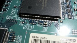
I was wondering though if there are good known locations where a reset wire could be installed on any of the System 2x6 PCBs so that I could trigger a reset using the Pi once the disc and dongle have been swapped?

Also curious how dangerous it is to flip the 246/256 mode jumper while the system is powered on or if that could safely be done while the system is held in reset.
 
Also curious how dangerous it is to flip the 246/256 mode jumper while the system is powered on or if that could safely be done while the system is held in reset.
I believe it should be safe. I'm not 100% sure but it looks more like a dip switch in the shape of a jumper.

@brizzo should have more info.
 
I don't think switching it while powered would cause damage, but may cause a software glitch, or no change in behavior until reset/power cycle.

As for how to trigger a system reset, I took a look at the PS2 service manual schematics and there is a widely shared /RST net. In theory this should cross over to 2x6, but we need to locate an easy break out point and test driving the signal low.
 
Not sure if it's been mentioned but will the ATAPI ODE support HDD mode in addition to CD/DVD?
 
Decided to get this done asap for you to play with @twistedsymphony

Took apart a System 256 to investigate -- good news!

Was nice to find /RST marked on the pcb (that was easy!). Verified it against the PS2 schematics that this is the system wide shared /RST signal

sys256_reset_mod_1.jpg


Soldered some wires from /RST and GND test point to a momentary push button.

sys256_reset_mod_3.jpg

We're in action! Works to reset the entire system, just reset this sys256 over ten times and it restarts and boots the game without issue. This weekend I will test with usb dongle, holding reset active/low while programming dongle, then release/high to boot.
 

Attachments

  • sys256_reset_mod_2.jpg
    sys256_reset_mod_2.jpg
    186.9 KB · Views: 570
Excellent! So you just tie RST to ground to hold in reset?

I'm assuming this works on the 246C and 256. Do you have any of the older 246 variants to look at. I have a 246B here that could check.
 
So you just tie RST to ground to hold in reset?
Correct!

I do not have any older variants, only 256 and 246C. Opened up 246C and confirmed it has the same /RST label silk screened in the same place :)
 
The reset point on my 256 works great, I've been using it often.

I pulled the mobo caddy out of my 246b to see if it had a similarly labeled RST point and I couldn't find one, though I didn't really go too far in the disassembly.

it basically has a PS2 main board and then a "246 mother" board that plugs into it for all of the front panel and IDE connections
246b_0.jpg

246b_1.jpg

246b_2.jpg

Now a normal PS2 console has a reset button on it, the power button acts as a reset with a short push and powers off on hold... so we might not be able to hold the console in reset but we could probably trigger a reboot if we can figure out where that button normally goes to.

of course a proper RST point would be better :D
 
I am very confident we can locate /RST on the early 246 boards. We have schematics from early generation PS2 that is more or less same hardware configuration.

@theoddtech has offered to tear down his 246B and take high res photos for me to analyze and suggest where to connect /RST trigger
 
With help from @brizzo we found what I think is the best point, photo of my test below. It's on the 246 board, which came from a chip on the ps2 board with tiny tiny legs, and came over via the flat cable in the photo. The leg on that chip is gonna be the best long term point, there is a via next to it (symbolized by the red dot) that I hit for a quick test that works fine, but isn't a stable point.

xZ2oLoZyhL3WXc-xWwE_9U9stESvZhSdxMFMQ=w520-h694-no.png
 
Thanks for that. I've tested and it's working great on my system 246B

Here is how I have mine setup with some strain reliefs:

on the 246B I have a piece of kapton tape to keep vibrations on the solder joint to a minimum.
sys246b_reset_1.jpg

Then I gave the wire a bit of slack and tied it off around a stand off so any pulling or snagging of the wire gets put to the post instead of the tape/solder joint.
sys246b_reset_2.jpg

on the 256 I did something similar only instead of using a post I simply tied a not and tucked it under one of the heat-sync posts:
sys256_reset.jpg

on both systems I terminated the wire into a female dupont connector to minimize the chance of the wire shorting out against something when not hooked up.
 
Good stuff guys! Pretty exciting times for the System 2x6 hardware!
 
So I'm curious about hooking this up to the Raspberry Pi. I'm not really sure what's safe on the RST line or what else uses it...

The Pi's GPIO pins are 3.3V. I'm not sure if it's safe too hook directly or if we should be using a solid state relay to so that when it's not being held in reset it's not pulling it high either.

I think a SSR might be needed for the 246+/256 jumper as well.
 
I would suggest using transistor logic to activate RST as it is an open collector input. I haven't investigate how the 246+/256 mode switch works, but I assume it is also open collector but will need to verify first.
 
I haven't investigate how the 246+/256 mode switch works, but I assume it is also open collector but will need to verify first.
I could be wrong but I believe the mode switch isn't a simple input. one pin is tied to ground but I believe the other goes to a crystal.
 
Back
Top