I've been wanting to get my hands on some Cyberlead LED display panel equipment so that I can attempt to document it and perhapse control it the same way I have with the Sega Versus Billboard displays: VS Billboard Output from Sega ST-V/Model 2/Model 3/NAOMI
Thankfully some of this equipment came up for sale recently and I bought it.
The Plan
The Plan is pretty similar to what I did with the Vs Billboard:
Phase 0: figure out how to wire everything up
Phase 1: build harnesses and get everything wired up and working
Phase 2: document PCB variations compatibility and game support
Phase 3: determine communication protocol
Phase 4: see what I can do with the information from Phase 3 and go from there...
@PascalPs thread here has a lot of useful information: JVS I/O error
The Components in this setup:
I've started to document the various Components:
Namco JVS IO that are "LED Ready" (require a separate LED control board):
8699014200 (8699011104) [CL1 I/OB] - Cyberlead JVS IO V1.02
8699014200 (8699011104) [CL1 I/OC] - Cyberlead JVS IO V???
8699014200 (8699011104) [CL1 I/OD] - Cyberlead JVS IO V???
Namco LED Control board (looks nearly identical to the JVS IO but without all the JVS equipment)
8699014500 (8699011104) [CL1 LEDA] - Cyberlead LED PCB
Namco JVS IO with built in LED panel output:
8903960302 (8903960302) [CLS1 AMI-B]- Cyberlead JVS IO V3.0
LED Panels:
RX1-696A [Red LEDs] - Cyberlead Dot Matrix Display
RX1-696A [White LEDs] - Cyberlead Dot Matrix Display
RX1-696B [White LEDs] - Cyberlead Dot Matrix Display
If you know of other versions of these PCBs please post them here with photos and I'll add them to the list.
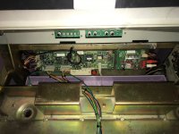
Wiring Information:
PascalP made a great diagram simplifying the setup:
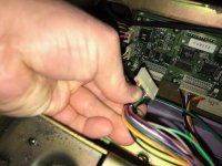
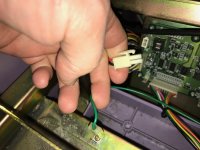
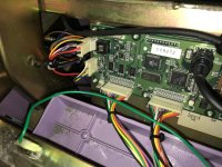
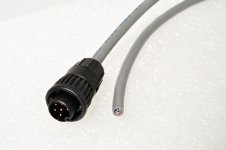
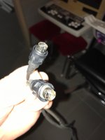
What I've discovered so far is the circular serial connector that ties the JVS IO to the LED control board is a 6-Pin Mini-DIN connector. these are easy to come by since they were used on old PS/2 computer keyboards and mice... HOWEVER the manual shows that two of the pins are swapped on the Cyberlead version of the cable (TX and RX).
I'm still trying to identify the power connector and the control panel connectors on this PCB... mostly the power connector. If anyone knows the model number of the 2-Pin connector in the corner please let me know. Once I have this I can build a power harness and start experimenting.
Thankfully some of this equipment came up for sale recently and I bought it.
The Plan
The Plan is pretty similar to what I did with the Vs Billboard:
Phase 0: figure out how to wire everything up
Phase 1: build harnesses and get everything wired up and working
Phase 2: document PCB variations compatibility and game support
Phase 3: determine communication protocol
Phase 4: see what I can do with the information from Phase 3 and go from there...
@PascalPs thread here has a lot of useful information: JVS I/O error
The Components in this setup:
I've started to document the various Components:
Namco JVS IO that are "LED Ready" (require a separate LED control board):
8699014200 (8699011104) [CL1 I/OB] - Cyberlead JVS IO V1.02
8699014200 (8699011104) [CL1 I/OC] - Cyberlead JVS IO V???
8699014200 (8699011104) [CL1 I/OD] - Cyberlead JVS IO V???
Namco LED Control board (looks nearly identical to the JVS IO but without all the JVS equipment)
8699014500 (8699011104) [CL1 LEDA] - Cyberlead LED PCB
Namco JVS IO with built in LED panel output:
8903960302 (8903960302) [CLS1 AMI-B]- Cyberlead JVS IO V3.0
LED Panels:
RX1-696A [Red LEDs] - Cyberlead Dot Matrix Display
RX1-696A [White LEDs] - Cyberlead Dot Matrix Display
RX1-696B [White LEDs] - Cyberlead Dot Matrix Display
If you know of other versions of these PCBs please post them here with photos and I'll add them to the list.
Wiring Information:
PascalP made a great diagram simplifying the setup:
The Cyberlead Manual has a more detailed explanation: https://wiki.arcadeotaku.com/w/File:Namco_Cyber_Lead_Manual.pdfSo I made a small overview of the situation of how everything is connected:


What I've discovered so far is the circular serial connector that ties the JVS IO to the LED control board is a 6-Pin Mini-DIN connector. these are easy to come by since they were used on old PS/2 computer keyboards and mice... HOWEVER the manual shows that two of the pins are swapped on the Cyberlead version of the cable (TX and RX).
I'm still trying to identify the power connector and the control panel connectors on this PCB... mostly the power connector. If anyone knows the model number of the 2-Pin connector in the corner please let me know. Once I have this I can build a power harness and start experimenting.

")
