What's new

West

Grand Master
Joined
Jul 24, 2015
Messages
648
Reaction score
993
Location
Brooklyn, NY
Hey AP folks,

I have a 4 gear Taito spinner I've been using and I'm finding that it generally feels too sensitive ie. a little rotation in the spinner creates a lot of movement in the game. So I've been thinking about ways to reduce the sensitivity.

The first way would be to adjust the gearing but I honestly don't want to get into that unless all else fails.

Another thought I had was to adjust the encoder wheel, and by that I mean modifying the openings/gaps in the wheel. Here's a pic of the wheel. If I were to for simplicity's sake, electrical tape over every other opening in the wheel, would that make it half as sensitive as it is now? Or could I 3d print another wheel with an different type of gap distance to achieve what I'm looking for?

Thanks for any thoughts or advice on this.

West


IMG_8857.jpg
 
Last edited:
An easy trick is to use LS74 latches to divide pulses frequency by a multiple of 2. One latch => ÷2, two latches in cascade => ÷4, etc.

But your mechanical solutions work too.
 
Thanks for the idea Apocalypse.

Forgive me as my electrical engineering skills are fairly rudimentary but to accomplish what you're describing would one basically take one of these chips:

https://www.digikey.com/products/en...tity=&ColumnSort=0&page=1&stock=1&pageSize=25

And wire the input and output pins of the chip between the (as in the diagram I've drawn) the left wire, and ground and vcc goes to appropriate pins on the chip. Then do the same thing for the right wire? Is it that simple?
spin.png
 
It's just a little bit more complicated, the 74LS74 contains two latches, very convenient since you have 2 signals to be frequency divided:
- spinner signal is used as CLOCK signal (pin 3 for first latch, 11 for second latch)
- signal /Q is fed back to input D (pin 6 connected to pin 2 for first latch, 8 to 12 for second latch)
- clear signals must be tied to Vcc (pin 1 for first latch, 13 for second latch)
- preset signals must be tied tied high or low (doesn't really matter, pin 4 for first latch, 10 for second latch)
- then you get the frequency divided by 2 signals on pin 5 for first latch, 9 for second latch (Q signals)

[EDIT]
Small schematic here:
https://www.electronics-tutorials.ws/counter/count_1.html
 
@Apocalypse You rock man!

Thank you. I'm gonna give this a try. One last question, should the IC I use for this be a D-Type Addressable or D-Type Transparent logic type?
 
Hey @Apocalypse

I picked up a few 74LS74 chips and read through the links you posted. Thanks for putting me on the right track.

I'm still a little confused as to what to do with the CLR and PRE pins on the chip?

For pin1 (CLR) you mention: clear signals must be tied to Vcc
For pin4 (PRE) you mention: preset signals must be tied tied high or low

I drew a quick diagram of how I'm interpreting it to be wired based on the instructions you sent through. The green lines of course represent the left spinner wire, I've colored them lighter and darker green purely to show separation.

Screen Shot 2019-04-26 at 3.43.11 PM.png


Thanks for any thoughts
 
@West this is correct.
Simply tie /PRE and /CLR to Vcc.
Then apply the same logic to the second signal coming from the spinner.
 
Thank you dood. All clear now. Gonna get these spinners dialed in ;)
 
That is the same circuit I built in an attempt to divide down the pulse rate. But it does not function as intended and I do not understand why. It works, then doesnt work, then glitches out, then speeds up and down, bizarre behavior. Didn't put much effort into trying to solve why.

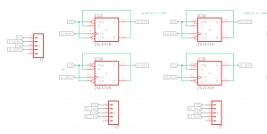
Here is my schematic for reference:

spinner divider.PNG
 
Nice one @brizzo. It makes sense to me now what your schematic is trying to do. Thanks for posting it up as it seems to be a great solution for adjusting spinner sensitivity to varying degrees. Maybe something to integrate into your joystick to spinner board v2.0?

As to why it’s acting erratically, I wish I had the skills to diagnose it. Seems straightforward in principle but clearly something is amiss from what you’ve described.
 
Last edited:
But it does not function as intended and I do not understand why. It works, then doesnt work, then glitches out, then speeds up and down, bizarre behavior. Didn't put much effort into trying to solve why.
I've experienced a similar issue if the load on the Q output is too high. Don't ask me why but I've proven it to be the issue by using simple resistors and even respecting the fan out wasn't enough to make it work.
I ended up buffering the signal and it worked like a charm.
 
nice timing, I was just thinking about making an little pass-though box to adjust trackball sensitivity. Sonic arcade, Rampart, etc. all seem way to slow for me.
 
@codecrank I don't think the solution described above could be used to increase sensitivity unless I'm missing something.

If you want to increase sensitivity of a trackball/spinner I imagine you'd need a chip to multiply the clock signal rather than divide it and I defer to @Apocalypse and @brizzo for which chip might do that.

Just throwing darts but maybe something along these lines?
https://www.swharden.com/wp/2016-08-31-ics501-simple-frequency-multiplier/

What looks cool about that IC is that it can output 2x through 8x the input clock signal. Lots of control from a single chip.
 
I've made a small circuit with a simple TTL chip before to double frequency.
I used it to create a 48MHz clock out of a 24Mhz one.
Let me see if I can find schematics.
 
I didn't mean that circuit directly , but something along those lines. Would be nice to have a pot to adjust the sensitivity.
 
Ok, so i'm messing something up here. Either the wiring is wrong, or maybe I've overheated the ic soldering wires directly to it, but I wanted to post this full diagram to see if I'm doing something wrong here per the diagram.

Thanks for any thoughts as to what I might be muppeting up are appreciated.

Screen Shot 2019-04-29 at 3.01.06 PM.png
 
Your diagram is correct.
Can you do some tests?
Unplug the wire coming from the spinner (left or write), unplug the corresponding wire going to the board (/Q signal) and manually generate pulses on the clock input. For 2 pulses on the input you should have one on the output (output changes state upon each pulse).
 
I think I need to get an oscilloscope ;) I'll run some tests and see what kind of results I can report.
 
Just use a logic probe or a multimeter. Each time you make a pulse on the clock input, outputs must switch to the opposite state.
 
Back
Top