What's new
Hey man, I'm starring you on git for some time. I made a code to fix the retrotronik psxtoneo adapter some months ago and figured that port manipulation could be used too after looking at your code, just changed the ports. I want to thanks for that. I was thinking about implementing FRAM for saving the buttons mapping, I mean, a external memory so I won't waste the internal EPROM and saw that you used it now. What you think about the degradation?
The code is written such that the EEPROM is only read at startup, and only written to when you change buttonmaps. I believe the EEPROM is rated for at least 100,000 read/write cycles so I doubt it would be an issue.

Also the credit for the direct port manipulation goes to @RGB not me. My code originally set the outputs high and it was RGB who offered an example of how to use port manipulation to set the outputs as open drain. I simply extrapolated from there.
 
Last edited:
Oh i see, thanks you both so.

My FRAMs are still missing on Brazil's customs so I may give a try o EEPROM library, just want to figure out how use.
 
Looks like I found some extra time.

3fc784bce3881a133b0b333850e5f4ad.png
5467e1400b3d0614776b349abdc90e52.png


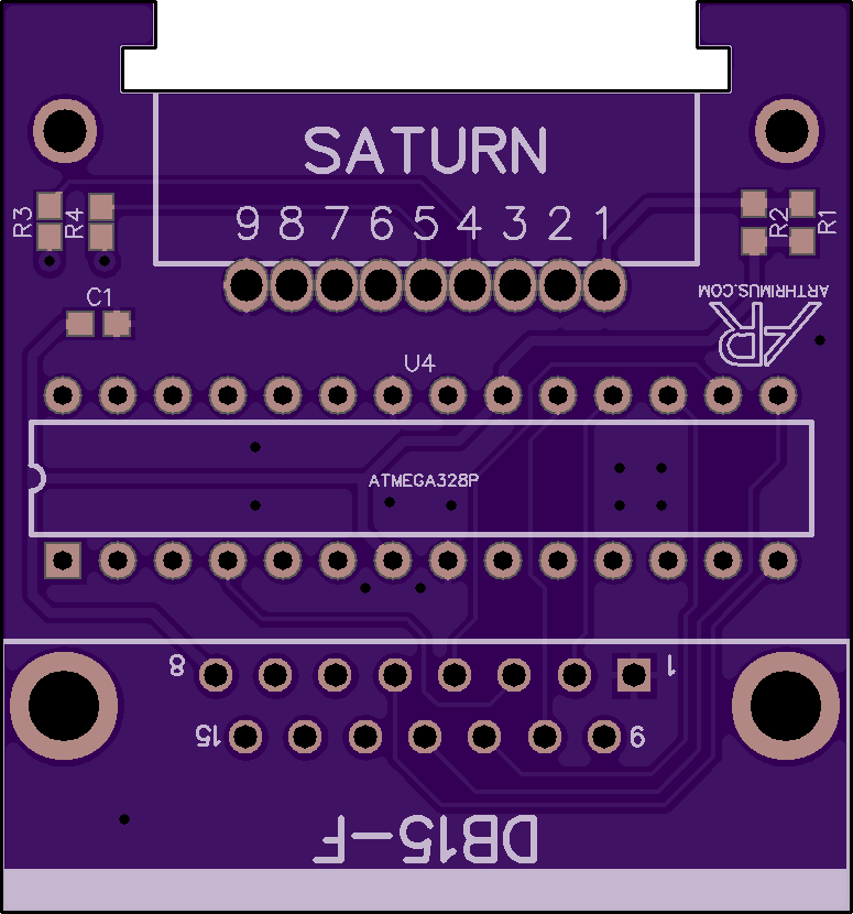
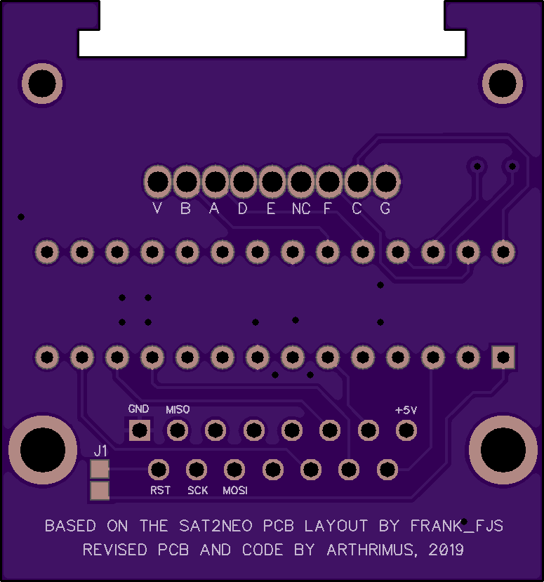
The routing is kind of a mess, I didn't want to have to do separate code for the DIP version. The original pinout made much more sense with the TQFP chip. It's not pretty, but it should work fine.

This code should work on ATMEGA 8/48/88/168/328 variants, so choose whatever you can get cheapest and easiest. You have to set the fuse bytes on the chip for 8mhz internal clock. I use a USBASP with a DB15 adapter to ISP program the board from the Arduino IDE. I use Minicore in the boards manager to set everything correctly.

Oshpark Link for the board files.
 
Last edited:
I'm going to try the SMD version first, ordering parts now.

Guessing C1 is a 0603 0.1uF capacitor? Pretty confident it is, it's not listed in the BOM however.
 
@Arthrimus

Have ordered both PCB types, will let you know how I go.

Quick qu: Possible to grab a compiled file such as HEX for programming?

I think I'll be fine without it, but it would still be handy to have.
 
@Arthrimus

Have ordered both PCB types, will let you know how I go.

Quick qu: Possible to grab a compiled file such as HEX for programming?

I think I'll be fine without it, but it would still be handy to have.
Cool, let me know if you have any issues. I think I can compile a HEX file, but I think the fuse bytes have to be set manually if you burn a hex instead of using the Arduino IDE. I'm not sure what needs to be set in that case. At the very least the 8mhz internal oscillator has to be enabled for it to work on my PCB.

Also I updated the code on my github. I finally buckled down and figured out a solution for full on the fly button remapping. For the remapping interface I took inspiration from the HAS button remapping interface. The way it works is you hold any 2 face buttons and Start simultaneously for 3 seconds and you enter button remapping mode. From there you press each button the number of times that corresponds to the output button you wish to set. For example a standard 6 button map would look like this.

X = 1 Press
Y = 2 Presses
Z = 3 Presses
A = 4 Presses
B = 5 Presses
C = 6 Presses

Whereas a reversed layout would look like this.

X = 4 Presses
Y = 5 Presses
Z = 6 Presses
A = 1 Press
B = 2 Presses
C = 3 Presses

Here is a demonstration live stream I did earlier this evening. Unfortunately Youtube cut off the first 30 seconds of the stream but not much was missed.
 
Why not map one of the L / R buttons to select (coin)? They're 2 x extra buttons that aren't needed and coin is frequently enough required to warrant an easy single button press to trigger.
 
I suppose I could add the option for that. I like it the way it is currently, but it would be trivial to make the coin method user selectable.
 
I like it too, it's more than enough as it is.

Just curious as to if there were a reason not to utilise the L / R buttons? Are they mapped to anything else if either button is pressed on its own? I'm just thinking that arcade has 6 inputs max, and they're covered by the ABCXYZ face buttons...
 
No reason in particular. I just didn't care for having the coin button so easily available. It seems like it would be distracting to accidentally bump one of the triggers and insert another coin. Maybe that's an unfounded concern, but that's what I was thinking at the time.
 
The timing on the Saturn's select lines is odd. The period of time that each select line is held high or low is not consistent. I don't have exact timings recorded anywhere, and I don't really have time to set up a test rig for it right now, but as I recall it cycles between 3 of the 4 select states very quickly, and holds on the last select state for a longer period of time. I assume that the gap in the select pattern is meant to accommodate more advanced controller protocols like the 3d pad, but I don't know much about those. I suspect that the chip being used by the Retro Bit controller is an off the shelf microcontroller of some sort, and is probably sensitive to the select timing of the Saturn.

I ran into a similar problem trying to get the Brook Retro Board working with my own Saturn to DB-15 adapter code, and adding the gap in the select timing fixed the problem. I can confirm that the Retro Bit controller does work with my adapter code also.

@twistedsymphony Perhaps try adding delay to the select pulses in your code. If I remember correctly the Saturn cycles through all of the select lines at around 90Hz.


With all of that said, I went ahead grafted an ATMEGAXX8 microcontroller onto @Frank_fjs's superior PCB layout that will work with my Arduino based Saturn pad demuxing code.

The Oshpark link contains the BOM.
Here is a link to my Github repository for the Arduino code.

mtTvwzp.jpg
Hey, this is cool that you are porting your code to the same layout. I don't understand how R1 and R2 are wired on your board though.
 
What else would I need to upload the code to the atmega328? An USBASP? I already have an Arduino Uno.
 
Hey, this is cool that you are porting your code to the same layout. I don't understand how R1 and R2 are wired on your board though.
I'm not sure what you mean. Are you talking about resistors R1 and R2? If so, they are in parallel and are only there for current limiting in case of a short circuit in the controller cable.


What else would I need to upload the code to the atmega328? An USBASP? I already have an Arduino Uno.
If you are planning on running the code on an Uno, you can just upload the sketch directly to the Uno through serial. If you are going to use either of my custom PCB designs you will need to us an ISP programmer to burn the code to the chip, and set it to use the internal 8mhz oscillator. You can use a USBASP or you can use the "Arduino as ISP" sketch on an Uno. You will want to install "Minicore" in your boards manager to make it easy to set everything up properly for your chip.
 
@Arthrimus , sir...can top3000 be used instead USBASP? Thanks
Unfortunately I don't have a top3000 so I don't know if Atmegas are supported or how to set up the programmer to write the correct fuse bytes. Maybe someone else has experience with this?
I can open the Top3000 and search for the Atmega chip , and see if these are supported...
 
I've not tested with this particular item however can tell you that the Top3000 does indeed program Atmel chips and is able to set fuse bits.

Personally I use my Mini Pro to program Atmel chips and specify fuse settings, works great and it opens INO files fine. Again, I've not tested with this adapter as I'm still awaiting PCBs to arrive.

My chosen USB ISP software is unable to read INO files and requires HEX or BIN files otherwise I'd have used it with my ISP programmer.
 
Back
Top