What's new
I don't think it's the PCB, in regards to fabrication.

I could very well have made an error. The schematic could be wrong, or it's a component that's causing an issue.

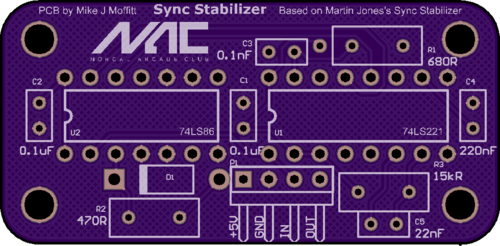
I will upload the PCB file tomorrow, it was created with FreePCB. Then others can examine the wiring and we can make a determination on if I've routed incorrectly.
 
Perhaps not a huge help, but here are some similar PCBs made by Silverfox over on UKVAC.
I eyeballed the topside traces but nothing stands out to me...

Img_8106as.jpg


And here is an update to the schematic to include H+V sync combiner on the unused gates on IC2
Yes, yes, fix v1 before adding features. (Credit philmurr, UKVAC)

Sync_cleaner.JPG
 
I see +5v going into IC2 pin 14 (the last pin). As far as I can tell, the only signal inputs IC2 receives is into pins 1, 2, 12, & 13. This is coming from the right leg of the 100nF decoupling capacitor. Then +5v going from there to pin 1 of IC2 as schemed. From pin 1 of IC2, +5v is going to pin 14 of IC2.
Is this where the problem may be? And if this is the problem, might I just cut the trace going into IC2 pin 14 to solve the problem?


Nevermind. I see that is the Vcc pin on that IC.
 
Last edited:
Gerbs for my PCB are attached, and here is an Oshpark link.


At a glance, I see you guys are using 6.8k resistors instead of the 680 ohm resistor that martin's schematic specifies. That may be your problem.

On my board, some of the component names and pins in use are not identical to what he has, but it is electronically the same.
 

Attachments

  • syncfix.zip
    73.6 KB · Views: 208
Last edited:
He states the 680R is a mistake and it's supposed to be 6.8K.

That aside, I believe you may be correct. 6.8K is crazy high for the signal involved and the author of the schematic offers a rather sketchy explanation about the 680R / 6.8K discrepancy.

Worth a shot @acblunden2 - try replacing the 6.8K with a smaller value.
 
Won't be able to get to this until Thursday or Friday, but I'll find out soon if swapping out the 6.8k resistor for a 680ohm resistor does the trick. Seems weird that he became aware of the mistake but didn't update the schematic drawing.

Out of curiosity @caius, when you built the circuit, did you stick to the schematic for all the parts? Particularly R1 which is printed in the schematic as 680ohm?

EDIT: The eBay version uses a 6.8k ohm resistor as well. But that version and Silverfox's version above are capable of outputting H & V sync. Don't know if that matters. The plot thickens.
 
Last edited:
At this point I’m almost certain it’s just a Component issue. I’m gonna order some other components to try out.
 
I got a whole new set of resistors from a local old school electronics store here in San Jose. Will swap out the 6.8k resistor for the 680ohm resistor and report back tonight. If that doesn't work, will swap out all the resistors to the ones I just picked up which are carbon film +/-5% tolerance 1/4 watt.

Update tonight.
 
Go man go :D

I would also ask @cpsystem3 I believe he has tried the same circuit and one point or another for the same reasons as you. Maybe he can state if it worked for him.
 
I've seen a stabilizer working on his PFX personally... But I think I would have to ask him in person about it, he hasn't been active on AP in a while it seems.

Pretty sure it's all about the Discord for him now.
 
I've seen a stabilizer working on his PFX personally... But I think I would have to ask him in person about it, he hasn't been active on AP in a while it seems.

Pretty sure it's all about the Discord for him now.
Ask him when you get a chance. I need to come up to see you guys, hopefully soon.
 
I will say from my experience with the PFX, this doesn't work with every board, just the ones with picky sync.

I did some testing with 300wins a few months ago; normal boards that worked with the PFX with no problem gave me a no signal when paired with the sync generator. However, F3, toaplan, and taito boards that didn't sync before did. Even with they synced, still had pincushion issues.
 
Negative. Replacing the 6.8k ohm resistor with a 680 ohm resistor produced the same 'NO SIGNAL' error.

I have a working version of this generator from Hatsune Mike's original design, given to me by 300wins, that works flawlessly. But I don't think it is the PCB design. Frank and XianXi are highly competent engineers and it is too simple of a circuit to have messed up in two places. Like XianXi said, it is likely a components issue.

I don't think the resistors, caps, and the diode that I used are the problem. May just be the Texas Instruments versions of these two IC's are at fault. Looking around the net at the few working productions out there, everyone else is using ON Semiconductor, Motorola, or some combination of different vendors for the two IC's. I am going to mess with what I have on hand tomorrow. Move the working components from Mike's PCB over to Frank's and vice or versa and report back. For the time being, I am going to remove the link to the Digikey project list I posted. If it is the components, don't want anyone getting those parts and running into the same problems.

@XianXi, can you confirm which manufacturer produced the IC's that you used?

On a side note, anyone know by the logo which manufacturer made this IC (it's the eBay version of the generator)?

s-l1600.jpg
 
Back
Top