What's new
https://imgur.com/a/tlCa4Sz

They actually fit but not comfortably. I’d bet 2mm does the job. Pics are 1) where I’d think they are comfortably fit, 2) showing that they fit if I pinch them in, and 3) showing that if pinched together and forced in, they bow outwards to compensate.

The encoders plastic has a little bit of variance but seem to be 41.7mm wide
 
@Frank_fjs Why don't you move the power led to the opposite side of the power connector and place the Test and Service buttons where the power led is currently located. If needed move the resistor further into the board a bit. The would give you plenty of space to move the controller port over.
 
Oh wow, it's not too far off. Brilliant, this will be simple to rectify.
 
@Frank_fjs Why don't you move the power led to the opposite side of the power connector and place the Test and Service buttons where the power led is currently located. If needed move the resistor further into the board a bit. The would give you plenty of space to move the controller port over.
Ideally I'd like the DB15s to be centred, as in evenly spaced from each edge of the PCB. As of now, they are each 30mm in from the edge when measured from the centre point of each DB15. I'm thinking if I shift them each 2mm closer to each edge, that will open up 4mm space between the centre of each DB15 thereby allowing 2 x UDs to fit.

My next planned add-on is a 4 player expansion board. This will work via a separate PCB which will have 2 x opposing DB15s (female) that will dock into the male db15s of the Minigun. On the opposite end of said expansion PCB will be the player 1 and player 2 DB15s, and on each side a player 3 and player 4 DB15. I'll add some form of header / connector (routed to the third and fourth player DB15s) to take a cable from the expansion PCB to the arcade game PCB.
 
Here's where I'm heading for version 2.0:
  • DB15s further spaced apart to resolve 2 x Undamned encoders not fitting side by side.
  • Tabs with 3mm holes added to each corner of the PCB to accommodate PCB feet / standoffs / mounting / plexi base attachment etc.
I believe this approach fixes the DB15 spacing issue and provides additional mounting options without comprising the DB15s being centred nor the general design and layout that I like. I might move the tactile switches to the farthermost right edge too. Any feedback welcome, the sooner the better before I begin finalising the design and fabricating some test PCBs.

MGUN-R2.png


Once I have the layout sorted, my next step will be a 3/4 player expansion board and down the track a video expansion board. The video expansion board will provide composite video, s-video, RCA audio output and a VGA connector designed for use with an OSSC.
 
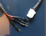
Does anybody have any suggestions on a 6 conductor power cable to go between the MiniGun and the PSU?

This braided one in arcadeqc's post looks really clean and perfect:
It looks like a molex connector/cable from a computer PSU?
 

Attachments

  • A4EBC839-22DF-45CE-BC5E-8348BD5362C1.jpeg
    A4EBC839-22DF-45CE-BC5E-8348BD5362C1.jpeg
    402.3 KB · Views: 189
Last edited:
Supergun wise, you won't damage anything at all regardless of trimpot settings. Display wise, probably not wise to turn the pots off. :) You will never exceed what the arcade board is outputting due to the termination but some devices may not like the TTL output.
Thanks again Frank. I'm trying my best to understand but a lot of this I just can't get through my thick head!

Hopefully one last(?) question... Does anybody know if the SCART cable included with the NESRGB will work OK with the Minigun and the OSSC? (I don't know if this SCART cable has resistors on the RGB or sync lines; it's tricky to get my multimeter on the 8-pin MiniDIN pins to check)

If so, how do I set the potentiometers correctly?

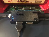
Here is my obligatory finished picture as well:
 

Attachments

  • IMG_0081.jpg
    IMG_0081.jpg
    873.6 KB · Views: 214
NES RGB cable is perfect. It doesn't contain any passive components and is the exact type of cable you need.

You can dial in the pots by eye and fine tune with a multimeter. Set your multimeter to measure DC voltage and probe each of the 3 x 75 Ohm resistors with the positive lead (the end of the resistor closest to the video connector) while probing the black lead to ground. Each pot should measure 0.4V on a Neo-Geo MVS colour bar test screen.
 
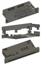
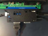
I just published the first release of a 3d printed case I designed for the Minigun supergun. This is designed and tested to fit the v1.7 "advanced" edition. I am also providing an untested version for the "standard edition."

https://www.thingiverse.com/thing:3807401

preview.jpg

I'm also making these available for 25$ shipped if someone is interested but doesn't have the means to print it. I'll forward a tip to Frank_fjs for every case sold.

connected.jpg

printed.jpg
Good Job man!
 
A hopefully quick question with a hopefully easy answer. When using the Undamned terminal block decoder (or even the DB-15 version) Does pin 9 get used for the D button for on an MVS, or is there something else I should do?
 
A hopefully quick question with a hopefully easy answer. When using the Undamned terminal block decoder (or even the DB-15 version) Does pin 9 get used for the D button for on an MVS, or is there something else I should do?
D should be pin 4 says the post over there
 
Yeah you're right, the problem ended up being user error. I forgot to move the switch for button 4. Sorry about that.
 
Batch of 1.7s on the way from JLC!

I'm planning to use a HD retrovision Genesis cable on this but didn't change the board up to din9, instead got a din9 jack and din8 plug from console5 to make a quick converter dongle for the cable.

Looks like the minigun din8 has a +5v pin so I can get power to the converter in the cable, think I need to attenuate the RGB/sync pins at all?
 
Here's where I'm heading for version 2.0:
  • DB15s further spaced apart to resolve 2 x Undamned encoders not fitting side by side.
  • Tabs with 3mm holes added to each corner of the PCB to accommodate PCB feet / standoffs / mounting / plexi base attachment etc.
I believe this approach fixes the DB15 spacing issue and provides additional mounting options without comprising the DB15s being centred nor the general design and layout that I like. I might move the tactile switches to the farthermost right edge too. Any feedback welcome, the sooner the better before I begin finalising the design and fabricating some test PCBs.

MGUN-R2.png


Once I have the layout sorted, my next step will be a 3/4 player expansion board and down the track a video expansion board. The video expansion board will provide composite video, s-video, RCA audio output and a VGA connector designed for use with an OSSC.
I'm not certain I like the tabs for the screw mounts. I'm going to have to rethink the design of my case to accommodate those, since I'm using the screw holes to bind it together. Or just have them sticking out of the case, if that's possible? I understand how they can be a cool feature for standoffs and they leave more room for the layout. I'm particularly worried that the tabs closest to the JAMMA connector my come in conflict with the screws coming from the JAMMA connector perpendicular.
 
Back
Top