What's new
4 player PGM
3 player AvP
3 player Moonwalker
4 player TMNT

Hell yeah!

I've got my cables ready. Man I hate crimping.
 
I tested my build tonight and have good results, but seem to have 1 problem. I may have an issue with the C-Sync. I can't adjust my monitor to stop rolling like crazy.

I toned out from pin 14 to the nearest resistor, so I think the TH chip is in there ok. (I actually toned out all the pins from that chip)

I do get voltage on the csync line, but I'm not sure what the proper voltage should be.

The RGB and Ground seem to be fine.

I'm hooking up to a 19" arcade CRT. I have tried plugging sync into positive H/V, negative H/V and not at all and I get the same exact result. Any thoughts on what I should check or voltage I should expect on the C-Sync line? (also, i split the csync to two pins like every post i've seen when hooking jamma up to an arcade CRT)

Also, i'm running 1.7 advanced.


Thanks!
Matt
 
Pin 14 is video ground.

P is sync, on the bottom layer.

That said, the Minigun attenuates video for a consumer CRT, an arcade monitor will be expecting TTL video levels. You can adjust the RGB pots to compensate, but there's no sync adjustment.

If you ONLY use it on an arcade monitor, best bet would be to adjust the resistors on the sync line or remove them, bypass the THS7374 circuit, and patch sync directly from the jamma edge.
perhaps a sync stripper with TTL output could help like the cheapo lm1881, ive been thinking about this option for my board.. (but i dont need TTL, I just like to have it handy for datapath video capture) or if your monitor needs rgbhv then @'Frank_fjs''s idea should work just fine. Alternative to the rgbhv idea you can use a fancy sync stripper like EL1883 or LM1980 which will output rgbhv from the rgbs (csync) source. ive used those in consumer crt tv's which need H+V to sync properly, or when converting rgbs to rgbhv for 15khz compatible LCD monitors (see 15khz wiki for model numbers)
 
LM1881 is good as it outputs TTL, well a bit below normal levels but close enough. About 3.5 volt, you lose some voltage in the cleaning process.

I will need to look into sync down the track, for Taito F3 / OSSC and video conversion to composite / s-video.
 
Thanks for the tip. Adding a jumper from P to sync yields a good picture. I wonder if there is a way for me to add a 5 pin RGBGS header pin to the layout as an arcade monitor is possibly a common setup for jamma test benches.
 
One idea, make a separate PCB with incorporated LM1881 (to boost sync back to TTL levels) with a mini DIN 8 connector on one end and a VGA connector on the other. Use a mini DIN 8 cable to interconnect between said PCB and Minigun, VGA to go to arcade monitor.

Thoughts?
 
4P adapter PCBs rolled in.

Never trust the internet.

I followed this pinout posted on junkerhq.net
Screenshot_2019-09-04-19-56-36-59.png

Which a cusory buzz of the multimeter verified. Where it's incorrect is the pin numbering. P3 COIN is pin 1 not pin 33.

Looking at the PGM IDC connector, the top right pin is pin 1, P3 COIN. The silkscreening on my PCB should tell the story.
69803307_10218097618085004_5357325279117180928_n.jpg

So it works but must be wired accordingly. Not really an issue for other games as you can wire up a harness to suit, but for PGM I want to utilise a standardised IDC cable so this needs to be fixed.
 
Hey guys,

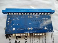
Just finished my rev 1.7 and thought I'd upload a couple of pics. I'm waiting on my RGC rgb scart cable and meanwell power supply to test, but it's one of the easier boards I've made.

Great work Frank_fjs

IMG_20190904_170603193_HDR.jpg
 

Attachments

  • IMG_20190904_170638200_HDR.jpg
    IMG_20190904_170638200_HDR.jpg
    954 KB · Views: 288
Last edited:
I just finished putting together a v1.7.

Thanks Frank_fjs!

How would you feel about screening the version number of the PCB on the front in addition to the back? I think it might be helpful when looking at the pics people post to know what version they are working with. Just a suggestion.
 
Thanks for the feedback everyone.

Loving the pictures, 2.1 looks nice even if I do say so myself.
 
@Frank_fjs after messing with 2.1 and 1.7 personally, aside from the converters fitting, 2.1 is just much nicer through and through
 
@Frank_fjs after messing with 2.1 and 1.7 personally, aside from the converters fitting, 2.1 is just much nicer through and through
How do you feel about the jumpers for LPF and audio?

Any trouble getting the voltmeter to fit / mount / soldered in?
 
The jumpers are absolutely fine.

The voltmeter was a pain in the ass. I cut and stripped the wires really short, to feed through the holes, and I had the hardest time getting the conductor through cuz the holes are so tiny. I feel they should be slightly bigger. Otherwise it's fine. I just got some brass spacers to mount it.

I feel with the power terminal change, it seems to be much easier to grip the minigun and pull it off the game pcb. I felt that with 1.7, I had nothing to grip to really loosen the board without feeling like something was gonna break. Not sure if anything else was at play, design wise, it just feels easier to deal with
 
I think it would be nice to space the voltmeter vias so that a 2 pin connector could be used alternatively. This would help with building the unit for people. Personally, I don’t have trouble installing it with the current design, but I do leave a bit of slack to help with putting everything together.
 
1.7 working great! Really well thought out and easy to build, appreciated the RGB tuning pots!

Just finished doing a Darksoft multi on a Marvel vs. Capcom B board with it. First time doing SMT, just took my time with a TS100 and fine tip and it worked out.

I cut up a mini din 8 data cable and soldered to a mini din 9 jack to use HD retrovision genesis cables into a retrotink. Man I never want to solder a mini-din connector of any sort again!

I ordered parts for 1-2 more but you're so fast with revisions and I hate the din soldering enough I'm thinking of doing another PCB based on v2.1 and maybe altering it to din 9/megadrive2 pinout. Next up is a MVS w/ 161 in 1 and then a pacman when I sort out the vertical monitor!

Thanks again for making this available to us all!

gntT2yal.jpg


(and yes i messed up the switch positions and put the tall one where the not-tall one goes...)
 
@mdfverona I did that too, made an 8pin mini male to 9pin mini din socket for my hd retro Sega cable ^^ those things are quite versatile. Good idea on different PCB with 9 pin socket. I think quite a few people have those hd retro cables now.
 
Back
Top